


Punching shear
Punching shear is a type of failure that occurs
on slabs due to high localized loads. In flat slab, this occurs at the columns
supports, as shown in figure no:1. The dead and live load of the slab will
generate a high shear force around the column's support. If the columns are not
well reinforced or the cross-section of columns is not big enough, the punching
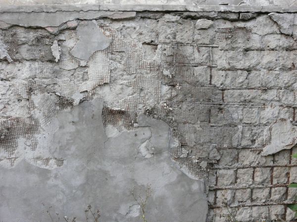
shear will occur. We can see in figure no:2 that the columns support failed due
to punching shear, the columns in this figure seem to punch and penetrate the
slabs.


For two slabs supported by beams and wall, shear
calculated at a distance equal d from the face of beam or wall, usually the
shear is not a problem for this type of slabs. On the other hand, for flat
slabs where the slab is supported directly by columns, the shear is a critical
factor in the design. The designer should check one-way shear and punching shear.
The critical section for punching shear is taken at a distance of d/2 from the
face of columns or the drop panel. The shear strength usually equal to ɸλ
bwd.


Figure 1

Figure 2
The designer should consider punching shear
during the design stage. The punching shear design will involve the following
steps:
·
Checking if the concrete is strong enough to
resist punching shear
·
If no, we need to add sufficient reinforcement to
resist punching shear
·
Or we can increase the concrete thickness
around the columns and this can be done by introducing drop panels, increase
the slab thickness or increasing the column cross-section.
If the shear stresses are plentiful around the
interior column, shear resistance can be increased by using of shearheads.
Shearheads consist of four I or channel beams fabricated into a cross-arm then
placed above the support, as shown in figure no:3. ACI code
states that the shearheads can’t be used to increase the shear resistance for
exterior columns. Therefore other methods shall be used for exterior columns.
Shearhead will increase the effective bo (perimeter
of the critical section for punching shear in slabs and footings) for the punching
shear. Also, it will increase the negative moment resistance for the slab. Another
type of shear reinforcement is the using of a group of bent bars or wires, as shown in figure no:4. The bars or wires are bent at 45˚ across the potential punching crack zone. The bent bars are extended at the bottom of the slab to a length sufficient to fully
develop the bar strength.

Figure 3

Figure 4
The using of shearhead will push the critical
section of punching shear away from the column, as shown in figure no:5. Pushing the
critical section farther out from the column will increase the area and provide
a larger perimeter to resist the shear.
According to ACI318-14[22.6.9.8], the critical section of the shear will
cross the shearhead arm at a distance from the column face
3/4*(lv-(c1/2))
Where
lv is the length of the shearhead arm from the centroid of the concentrated
load or reaction
c1 is the dimension of the rectangular or
equivalent rectangular column or capital or bracket, measured in the direction
in which moments are being calculated.

Figure 5


Comments
Post a Comment