Posts

Showing posts with the label mechanics of material

Subscribe to My You tube channel

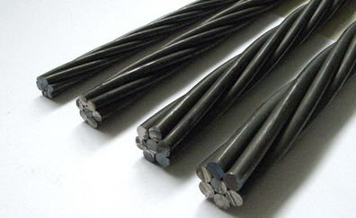
Ductility of reinforcing steel

Image
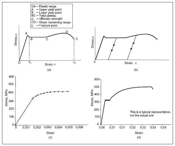
 Ductility is an important property of steel reinforcement. Ductility is the ability of the material to undergo plastic deformation before failure. The ductility of reinforcement is related to the elongation property. The ductility of reinforcement ensures safer and durable structures. Material that undergoes little or no plastic deformation is known as a brittle material. Brittle reinforcement can cause sudden structure failure because it doesn't undergo any plastic deformation before failure.  Figure 1 The ductility factor for reinforcement can be computed using the following equation: µ=ϵu/ϵy where, µ is the ductility factor ϵu is the ultimate strain ϵy is the yield strain In figure no:1-a, we can see the stress-strain curve for mild steel. The mild steel has well-defined yield stress and strain, as shown in the stress-strain curve. The reinforcing bar can recover all the elongation if the applied stress is lesser than the yield stress. This portion of the curve is known as the

Useful Engineering Courses

 Construction management: Road construction course This course is designed to expand your practical side of engineering knowledge. This course is concentrating on the construction of roads. Here you will learn how the road is constructed. The construction stages such as protection of existing services, clearing the area, future utilities, preparing the road subgrade, then placing different pavement layers such as sub-base, base course, and asphaltic courses. We will also discuss the types of asphaltic course and the common defects of asphaltic pavement, such as permanent deformation, fatigue cracking, and low-temperature cracking. Also, I will show a typical cross-section of road and road profiles and many other subjects. Enroll from here  Pile foundation design This course will discuss the design of pile foundations. We will learn the methods of calculating the pile bearing capacity. The bearing capacity for a pile consists of skin and end bearing resistance. Here you will understand

Effects of prolonged mixing of concrete

Image
Mixing of concrete for an extended period can adversely affect the properties of a concrete mix. Tests have shown that mixing air-entrained concrete for a period longer than 180 minutes can significantly reduce the content of entrained air. Air-entrained admixture used to prevent the damage of concrete due to freeze-thaw cycles in cold weather. The reduction of the content of air-entrained admixture will reduce the ability of concrete to resist the damage caused by freeze-thaw cycles.  Figure 1 The temperature of the concrete mixture will increase with the increase of mixing time. The friction effects due to mixing will result in an increase in concrete mix temperature. The workability of the concrete mix will also be reduced due to the prolonged mixture of concrete. The loss of workability occurs due to water evaporation from concrete. Moreover, higher mixing speed will result in a higher reduction of concrete workability. Reducing the concrete workability will resul

Tunnel lining systems-Ribbed system

Image
Ribbed supporting system has been used for many years to support tunnels. The ribbed supporting system is based on steel ribs supporting tunnels. The implementation of this system involves the installation of rolled steel sections around the circumference at specified spaces. The formation of gaps between the steel ribs and the ground is very common. These gaps should be suitably wedged to avoid excessive deformation of the ground. It is essential to ensure that the loads are distributed evenly by the steel support around the tunnel profile. Subjecting of steel support to point load will significantly reduce their ultimate capacity.  Figure 1 The steel ribs can be combined with shotcrete concrete. The shotcrete concrete will be applied before the erecting of ribs. The applying of a layer of shotcrete concrete will reduce the problems of gaps between ribs and surrounding ground, which minimize the wedging problems. Then another layer of shotcrete can be applied after th

Mechanical splicing of reinforcement steel

Image
As we know, the reinforcement steel length is limited. For long structural members, the reinforcement steel bars should be overlapped or spliced to produce the required length of reinforcement. Mechanical splicing of reinforcement is used widely in the construction industry. Threaded couplers are a widespread type of mechanical splicing. Threaded couplers are sub-categorized into taper and parallel threaded couplers. The cross-section and length of the coupler will depend on the grade of the reinforcement rebar. Taper threaded coupler is the simplest type of threaded coupler. This type of coupler can be used for columns and horizontal applications. But it is difficult to in rafts or other applications where it is difficult to turn and tighten the rebars. In general, the length of taper threaded couplers is more than parallel couplers. Taper threaded couplers are designed, taking into ac­count defects of the rebar such as undersizing, skewness, and oblongness of the rebar. 

Tube reinforced concrete

Image
Steel possesses high strength and ductility. Steel, as a structural member, especially as a compressive member such as columns, will have a limited stiffness. On the contrary, the concrete performs very well as a compression member. Concrete has excellent compressive strength and high stiffness. The combining of a steel tube and concrete to form a tube reinforced concrete will enhance the member strength, stiffness, ductility, and overall capacity. concrete-filled steel tube  (CFST)  is not just a steel tube with a concrete core. CFST will speed the construction process and enhance the load-carrying capacity and ductility of the structural members.  Figure 1 The tubes used for CFST can be a circular, square, or rectangular shape. However, the performance of circular CFST is better than other shapes. Also, the processing of a circular CFST is easier and cheaper than other shapes. A circular tube with a thickness of less than 20 mm will be welded using a spiral weldin

What is water hammer?

Image
Water hammer can be defined as a sudden increase of pressure inside the pipe due to the sudden change of direction or velocity of the liquid flowing inside the pipe. Water hammer can cause the rapture of the pipe and severe damage to the equipment.  construction management: concrete construction bridge construction:How to become a bridge engineer To explain the cause of water hammer, we need to understand that the flowing liquid has two types of energies: Kinetic energy and potential energy. The kinetic energy generated by the velocity of the fluid while the potential energy represented by the liquid pressure. Neglecting the friction inside the pipe, the combination of both energy is constant along the pipe length. A sudden change of liquid velocity will result in changing the kinetic and potential energy. If the velocity decreased, the kinetic energy will decrease. The decrease of kinetic energy will result in an increase of potential energy or in other word, t

Thermal effects in a structure

Image
stresses on structures are not generated only due to external loads, change in temperature will result in thermal stress and thermal strain due to contraction and expanding of structures, figure 1 showing a block, if we increase the temperature of the block and fixed the block at point A, as a result of heating the block will expand and the shape will be approximately similar to dashed lines, Figure 1 construction management: concrete construction bridge construction:How to become a bridge engineer For most materials, the thermal strain is proportional to change in temperature and can be computed using the following equation  ε T= ΔT* α where  α is the coefficient of thermal expansion, the unit for the coefficient of thermal expansion is (1/K or 1/C) ,   ΔT is the change in temperature for the structure. The strain assumed to positive for expansion and negative for contraction, the table below shows the coefficient of thermal expansion for some materi

Change in length for a bar with continuously varying load or dimensions

Image
sometimes the axial force and the cross-section area varies along the length of the bar. for this case the equation  δ=(PL)/(AE) will not be applicable ,  figure 1 shows a bar with continuously varying load and cross-section area along the length L, for P(x) acting at point A and varying along the length of the bar with force of PB at point B. the force acting along the bar is function of distance (unit of pound per inch or newton per meter).  A distributed axial load may be produced by such factors as centrifugal  forces, friction forces, or the weight of a bar hanging in a vertical position. Figure 1 construction management: concrete construction bridge construction:How to become a bridge engineer To compute the change of length for this case, we should integrate the change in length of a  differential element of the bar and then integrate over the length of the bar. in general the force is the function of x(change in length) as shown in figure b, the c

Changes in lengths for axially loaded members under nonuniform conditions

Image
For a prismatic bar loaded at both ends only, elongation or shortening can be calculated using this equation  𝛿=(P*L)/(AE). in some cases the prismatic bar will not be loaded only at endpoints, the load will be applied at an intermediate point as shown in figure 1. for such case we can calculate the change in length by  algebraically  summing the elongation or shortening of each segment Figure 1 construction management: concrete construction bridge construction:How to become a bridge engineer For a prisimatic bar in figure 1-a, the procedure will be as follows: determine the separate segments for the bar, segments AB, BC, CD. Determine the internal axial force at each segment N1, N2, N3 from the free body diagram. For first segment N1 from free body diagram (figure 1-b) N1=PD+PC-PB for second segment N2=PD+PC (figure 1-c) For third segment N3=PD (figure 1-d) then determine the change of length for each segment  𝛿1=(N1*L1)/(A*E),  𝛿2=(N2*L2)/(A*E),  𝛿3

Example 1: Changes in length of axially loaded members

Image
A rigid L-shaped frame ABC consisting of a horizontal arm AB (length b =10.5 in.) and a vertical arm BC (length c = 6.4 in.) is pivoted at point B, as shown in Fig. 1. The pivot is attached to the outer frame BCD, which stands on a laboratory bench. The position of the pointer at C is controlled by a spring (stiffness k = 4.2 lb/in.) that is attached to a threaded rod. The position of the threaded rod is adjusted by turning the knurled nut.  The pitch of the threads (that is, the distance from one thread to the next) is p =1/16 in., which means that one full revolution of the nut will move the rod by that same amount. Initially, when there is no weight on the hanger, the nut is turned until the pointer at the end of arm BC is directly over the reference mark on the outer frame. If a weight W = 2 lb is placed on the hanger at A, how many revolutions of the nut are required to bring the pointer back to the mark? (Deformations of the metal parts of the device may be disregarded because

Changes in length of axially loaded members

Image
Length of axially loaded members will change when they are subjected to axial load, members length will decrease when it is subjected to compression load, The length will increase for tension loads. to illustrate the concept we will begin with spring. Let consider spring in figure 1, assuming that this spring is subjected to tension force equal P, the length of spring before elongation equal to L. after applying the force the length will increase by  δ, the total length after elongation will be L+ δ. if the material is linearly elastic the load and elongation will be proportional P=k* δ ,  δ= f*P The constant k is the stiffness of the spring and can be defined as the force required to make a unit of elongation. the constant f is the flexibility of the spring and can be defined as the elongation produced by a load of unit value. k=P/ δ, f= δ/P k=1/f, f=1/k flexibility can be determined easily by measuring the elongation for a known force, from flexibility stiffness o

Design for axial load and direct shear

Image
design is the process that involves the determination of structure properties and dimension in order to support specific loads and perform it is function properly. the design process will determine the number and location of supports, materials to be used in the structure, properties of used materials, the dimension of structure members. The design process is tougher and consuming more times compared to the analysis process. in the analysis process, structure properties are given. this includes a full description of structure properties and members dimension and location. analyzing of a structure is done once and design of structures involving analyzing of structure. in analyzing or designing a structure. we use two important terms: loads and reactions. loads refer to active forces applied to the structure such as wind, gravity, and earthquake. the reaction is induced at support due to applied loads. magnitude and direction of reaction will depend on the magnitude and direction of a

Popular posts from this blog

Bar Bending schedule (BBS)

Binding wire for steel reinforcement

stress-strain diagram for aluminium alloy and rubber

Pile cap

Repairing of concrete bulging

Bridge Diaphragm

Nominal maximum size of coarse aggregate

Flakiness Index and Elongation Index of Coarse Aggregates

Tunnel lining systems-Ribbed system

Prestressing stands debonding

My photo
Mohammad
My name is Mohammad Hamdan, and I am a Civil/bridge Engineer with extensive professional background and experience in the field of construction. I have 10+ years of experience in the construction field. During my professional career, my emphasis has been placed on structural projects, mainly bridges, infrastructure and roads. Reading and practicing the design of structures is my passion.i was lucky to be a part of a big team that executed major highway interchanges. I believe in spreading the knowledge, thus, i compose these courses to share my experience and knowledge. My course focuses on the practical side of construction field. On other word, i am sharing some of what new engineers need to know about construction field. Beside working on construction field, i love writing some articles on my website ( curious civil engineer) Moreover, i wrote some engineering papers, you can check them  by searching my name on Google (Mohammad mamon Hamdan)