Posts

Showing posts with the label structure

Subscribe to My You tube channel

why do we use cranked rebar at rebar overlapping?

Image
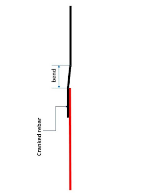
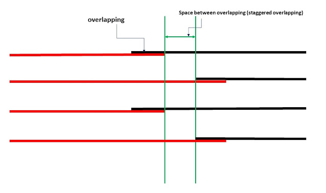
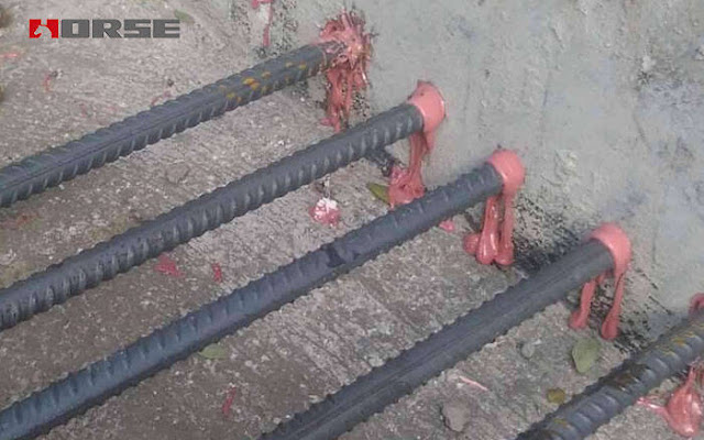
 Cranked bars are produced by slightly bending the reinforcement bar before the overlapping zone then straightening it at the overlapping zone, as shown in figure no:1. The main purpose of this practice is to reduce the congestion of reinforcement at the overlapping zone for structure members with a high amount of reinforcement. The use of crank bars will give flexibility in fixing and arranging reinforcement to reduce the congestion, which helps create a larger space between reinforcement rebars. The spacing between reinforcement rebars should be sufficient to allow smooth concrete placement. Small spacing of reinforcement rebar will work as a screen that will enable the concrete paste to pass through it and stop aggregate, which results in concrete segregation. Therefore, cranked rebars can be used to slightly reduce the congestion of reinforcement rebars and increase the spacing between rebars. Figure no:1

why do we stagger reinforcement overlapping?

Image
First, we should know that steel rebar comes in standard length such as 12m. using very long reinforcement is impractical because it will result in difficulties in handling reinforcement by steel fabricators. Also, longer rebar is heavier and difficult to lift and move. So for a long structure such as a slab, we require a reinforcement length that is more than the standard reinforcement. We can't use a single piece of rebar for a specific length for such a structure, so we use two or more steel rebars to cover the entire length of the structure. Figure no:1 The zone of overlapping between reinforcement will be considered as a weak zone. Therefore, it is a good practice to stagger the reinforcement overlapping. Staggering is done by overlapping the reinforcement at a different location. Staggering reinforcement overlapping will reduce the number of rebars overlapped at the same point, which will be beneficial in two ways. Firstly, it will reduce the discontinuity of rebar at the s

why do we overlap steel rebars??

Image
 First, we should know that steel rebar comes in standard length such as 12m. using very long reinforcement is impractical because it will result in difficulties in handling reinforcement by steel fabricators. Also, longer rebar is heavier and difficult to lift and move. So for a long structure such as a slab, we require a reinforcement length that is more than the standard reinforcement. We can't use a single piece of rebar for a specific length for such a structure, so we use two or more steel rebars to cover the entire length of the structure. Clearly, the point of joining these rebars is critical and weak. So, for this reason, and to prevent structure failure at this point, we overlap the reinforcement to ensure that there is sufficient length to transfer stresses at this point, which prevent: tension, pull-out, and shear failure at the location of joining the rebars. Figure no:1

Adhesive anchors

Image
 The use of adhesives for fixing anchors such as bolts, steel dowels increased recently. We can see many adhesive anchors in the market. However, not all products are suitable for the various adhesive anchoring applications. The anchoring of adhesive can be horizontally, downward, upward and inclined in terms of orientation. In terms of working environment, the adhesive anchors can be used in dry conditions, water-saturated and submerged conditions. Therefore, the selection of adhesive products should consider all these factors to ensure the durability and safety of used anchors.  Figure no:1 The adhesive anchoring system consists of adhesive material, anchors such as dowel reinforcing bars, drilling equipment, and the equipment used for cleaning such as wire brush and air compressor.  There is a various methods used for drilling the holes for adhesive anchors. the hammer drilling machine can be used to drill the hole. it is preferred to use the hammer drilling machine because it is pr

Classification of compression members for local buckling

Image
Compression sections are classified into non-slender and slender elements. A section is considered non-slender if the width-thickness ratio is larger than the value shown in the AISC B4.1a table, and it is shown in the table below. When the width-thickness ratio is less than the section will be defined as a slender element. Almost all the HP and W sections listed in the AISC manual for yield strength of 50 ksi are non-slender. The design value listed by AISC reflects the reduced design stresses available for the slender sections. If the member is defined as a non-slender element compression member, then, the nominal compressive strength is determined from AISC E3 on the limit state of flexural buckling. But if the member is defined as a slender element member, the nominal compressive strength will be determined from E7 of the AISC and it will be the lowest of the flexural buckling, torsional buckling, and flexural-torsional buckling.

Fiber Reinforced polymer for strengthening of reinforced concrete

Image
 Fiber-reinforced plastic (FRP) is a new technique to strengthen structures. Fiber-reinforced plastic has various types, such as a carbon-fiber-reinforced polymer (CFRP), glass fiber reinforced plastic (GFRP), and aramid fiber-reinforced polymer (AFRP).  The below table shows the mechanical properties of different fiber types.     Table 1 we can notice that carbon fiber reinforced polymer possesses better properties compared to other types. For example, the tensile strength of CFRP extra-high strength can reach 6200 MPA compared to a maximum tensile strength of 4135 MPA of other fiber types.   The FRP has various uses such as: Improved seismic performance of masonry walls Replacing missing steel reinforcement Increasing the strength and ductility of columns Increasing the loading capacity of structural elements Correcting structural design and/or construction defects Increasing resistance to seismic movement Improving service life and durability Structural upgrading to comply wit

Prestressing strand manufacturing

Image
  Prestressing strands is high tensile strength steel. The tensile strength of prestressing strands can reach up to 1860 Mpa. the process of manufacturing prestressing steel differs significantly from the conventional reinforcement.  Figure 1 The process of manufacturing strands will begin by de-scaling the raw material (wire rod). The purpose of de-scaling is to remove the iron oxides (mill scale) from the surface of the wire rod. after removing the mill scale, the wire rod's surface is coated with a textured coating to enhance the adherence of lubricants to the raw material surface. The most commonly used coating is zinc phosphate.  Figure 2 The wire rod then passed through a series of dies. The process of reducing the wire rod diameter is known as cold-drawing. In this process, the wire rod is drawn through a die with the required diameter. To prevent the wearing of dies, the wire rod will be drawn through a lubricant box. the lubricant will coat the wire with a thin layer that

Prestressing stands debonding

Image
  Prestressing bridge concrete beams contributes to resisting the tensile stresses caused by the traffic loads and the beam's weight. Stressing concrete has various benefits, such as increasing concrete members' capacity, reducing the concrete member section, and increasing the span lengths for structures such as bridges and buildings. However,  The stressing of bridge beam ends can result in unwanted cracks. Therefore AASHTO calling for debonding a specific portion of strands at the beam end to minimize the stresses and reduce cracks. Figure 1 Debonding is achieved by wrapping the strands at the end of the beam with plastic. Wrapping the strand with plastic wrapping will prevent the strands from bonding with concrete, thus avoid transferring unwanted stress to the beam end. As a result, the unwanted cracks will be prevented by reducing the stress levels at the end of the beam.  

Conjugate beam Problem no:6

Image
  Example 5: determine the force F, so the displacement at C will be zero assuming EI constant over the beam length? Figure 1 The first step is to draw the M/EI diagram for the real beam. The conjugate beam will be loaded with M/EI diagram for the real beam. The pin at A will stay the same for the conjugate beam while the internal roller at B will change to an internal pin for the conjugate beam. The free end at point C will become a fixed end. So the conjugate beam will be as shown in figure no:2.  Figure 2 To draw M/EI, we need to determine A and B's reaction for the real beam. Figure 3 So the shear and moment diagram will be as shown in figure no:4. Figure 4 Now, we will take section B-C. to determine FB using the equilibrium equation(MC=0). Figure 5 Now, we will take section A-B. to determine FB using the equilibrium equation. The FB computed from section A-B will be equaled to Fb calculated from section B-C to determine F related to P. To calculate a1 and a2, we will use the t

Nominal maximum size of coarse aggregate

Image
Concrete is a widely used material. Reinforced concrete structures can be found everywhere. The main reason behind the popularity of reinforced concrete structure is the high strength and the long life span of these structures. Concrete and steel are combined to produce reinforced concrete. Concrete is good at compression while steel good at tension. Concrete and steel form a perfect combination to resist loads imposed on the structure. Concrete is a composite material composed of cement, coarse aggregate, fine aggregate, and water. Admixtures can be used to enhance concrete properties. A concrete mix consists of almost 65% aggregates. Aggregates are classified into fine and coarse aggregates. Since the aggregates form the majority of a concrete mix. The quality of aggregates can greatly affect the strength and durability of concrete. Aggregates can be natural or crushed aggregates. Used aggregates should be strong, hard, and should not contain a large amount of organic matter or harmf

Conjugate beam Problem no:5

Image
Example 5: determine the displacement at C and the slope at point B for the beam shown in figure no: 1 considering EI a constant? Figure 1   The support at A for this beam will allow the rotation but no movement, so it is considered a pin, and it will stay the same in the conjugate beam. While the support at B will allow the movement in horizontal direction and rotation, it will be similar to the roller, and it will stay the same in the conjugate beam. So the real beam will be as in figure no:2. And the conjugate beam will be as shown in figure no:3. Figure 2 Figure 3 To determine the displacement at point C and the slope at B, we need to determine the moment at point C and the shear at point B in the conjugate beam. The conjugate beam will be loaded with M/EI of the real beam, so we need to draw M/EI for the real beam. To draw the M/EI diagram, we need to determine the reaction at point A and point B. From the symmetry we can know that the reaction FA=FB=P. so the shear moment diagram

Bar Bending schedule (BBS)

Image
 The bar  bending schedule is a table that contains the details of reinforcement for a specific structural member such as footing, column, slab, and others. The bar bending schedule will contain the bars' dimensions to be used, the shape of the bars, the size of bars, bar mark, number of bars, and the weight of bars. BBS will be used to determine the weight of reinforcement required for a specific structural member.  there are various advantages of bar bending schedule such as: estimating the quantity of reinforcement for each structural member. So we can estimate the amount of reinforcement required for a construction project.  BBS will help in reducing the losses of steel by procuring the precise quantity of different rebar diameter.  BBS will reduce the wastage of reinforcement by providing the engineers with the exact dimension and shape of rebars. Knowing the exact dimension and shape will reduce the time of cutting and bending rebars.  BBS will reduce the effort at the time o

Conjugate beam Problem no:4 (Beam with internal pin, roller and point load )

Image
Example no:4: find the displacement at point C and the slope at point B for the beam shown in figure no:1. Figure 1 The conjugate beam will be, as shown in figure no:2. The pin and roller at A and B will become internal pin. The free ends will become fixed, as shown in figure no:2. We need to determine the M/EI diagram for the real beam, which will be the load in the conjugate beam, to determine the displacement at point c and slope at point B. Figure 2 To draw the moment diagram for the beam, we need to determine the reaction at point A and B, then draw the shear diagram and the moment diagram. Using the equilibrium equations: Figure 3 The shear and moment diagram will be, as shown in figure no:4. Figure 4 The conjugate beam will be loaded, as shown in figure no:5. Figure 5 To determine the displacement at point C, we need to determine the moment in the conjugate beam at point C. to determine the moment at point C, we will take section A-B to determine the force at B. Figure 6 Now we

Popular posts from this blog

Bar Bending schedule (BBS)

Binding wire for steel reinforcement

stress-strain diagram for aluminium alloy and rubber

Pile cap

Bridge Diaphragm

Repairing of concrete bulging

Nominal maximum size of coarse aggregate

Flakiness Index and Elongation Index of Coarse Aggregates

Fire resistive construction-firewalls

Prestressing stands debonding

My photo
Mohammad
My name is Mohammad Hamdan, and I am a Civil/bridge Engineer with extensive professional background and experience in the field of construction. I have 10+ years of experience in the construction field. During my professional career, my emphasis has been placed on structural projects, mainly bridges, infrastructure and roads. Reading and practicing the design of structures is my passion.i was lucky to be a part of a big team that executed major highway interchanges. I believe in spreading the knowledge, thus, i compose these courses to share my experience and knowledge. My course focuses on the practical side of construction field. On other word, i am sharing some of what new engineers need to know about construction field. Beside working on construction field, i love writing some articles on my website ( curious civil engineer) Moreover, i wrote some engineering papers, you can check them  by searching my name on Google (Mohammad mamon Hamdan)