Posts

Showing posts with the label Design

Subscribe to My You tube channel

why do we overlap steel rebars??

Image
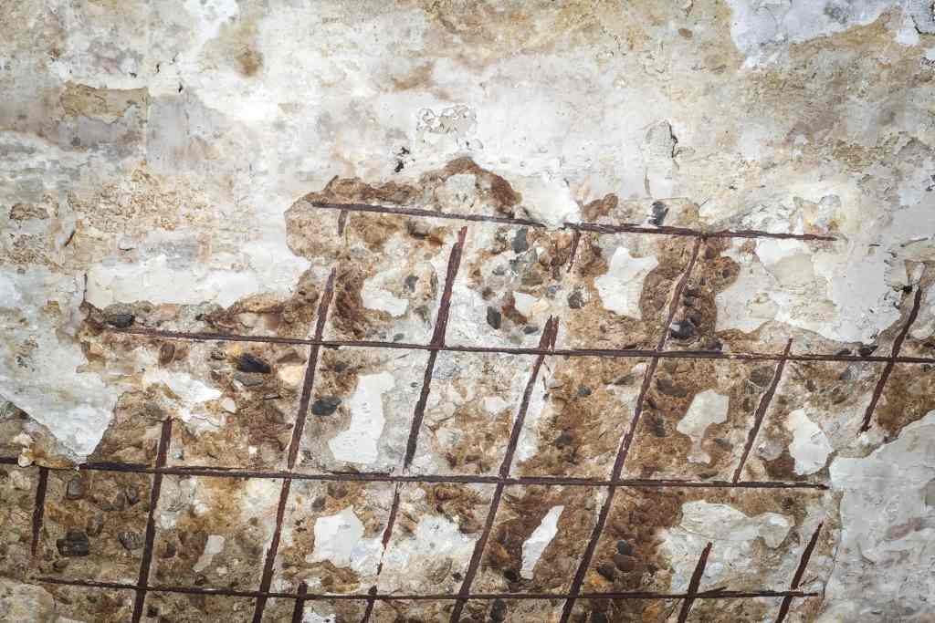
 First, we should know that steel rebar comes in standard length such as 12m. using very long reinforcement is impractical because it will result in difficulties in handling reinforcement by steel fabricators. Also, longer rebar is heavier and difficult to lift and move. So for a long structure such as a slab, we require a reinforcement length that is more than the standard reinforcement. We can't use a single piece of rebar for a specific length for such a structure, so we use two or more steel rebars to cover the entire length of the structure. Clearly, the point of joining these rebars is critical and weak. So, for this reason, and to prevent structure failure at this point, we overlap the reinforcement to ensure that there is sufficient length to transfer stresses at this point, which prevent: tension, pull-out, and shear failure at the location of joining the rebars. Figure no:1

Conjugate beam Problem no:4 (Beam with internal pin, roller and point load )

Image
Example no:4: find the displacement at point C and the slope at point B for the beam shown in figure no:1. Figure 1 The conjugate beam will be, as shown in figure no:2. The pin and roller at A and B will become internal pin. The free ends will become fixed, as shown in figure no:2. We need to determine the M/EI diagram for the real beam, which will be the load in the conjugate beam, to determine the displacement at point c and slope at point B. Figure 2 To draw the moment diagram for the beam, we need to determine the reaction at point A and B, then draw the shear diagram and the moment diagram. Using the equilibrium equations: Figure 3 The shear and moment diagram will be, as shown in figure no:4. Figure 4 The conjugate beam will be loaded, as shown in figure no:5. Figure 5 To determine the displacement at point C, we need to determine the moment in the conjugate beam at point C. to determine the moment at point C, we will take section A-B to determine the force at B. Figure 6 Now we

Conjugate beam Problem no:1 (beam with pin and internal roller)

Image
 Problem no:1, Determine the slope and displacement for the following beam at point C? Figure 1 In this example, the pin support will stay the same in the conjugate beam. While the roller will change to hinge and the free end to a fixed support. So the conjugate beam will be the same as shown in figure no:2. Figure 2 Now we need to determine the moment diagram for the real beam.  First step is to determine the force at support A and B by the use of equilibrium equations: Figure 3 Now we can draw the moment diagram for the real beam. To draw the moment diagram, we can draw the shear first, and the moment diagram will be the area of shear. The moment diagram for the real beam will be, as shown in figure no:4. Figure 4 After drawing the shear and moment diagram, our conjugate beam will be loaded with the M/EI diagram of the real beam, as shown in figure no:5. Figure 5 now to determine slope and displacement at c we need to calculate the shear moment at c by the use of equilibrium equatio

Conjugate-Beam method for determination of beam deflection and slope

Image
 The Conjugate-Beam method can be used to determine the deflection and slope for beams. In this method, the shear in the conjugate beam at any point will be the real beam slope at this point. While the moment in the conjugate beam will be the displacement of the real beam at the same point. The conjugate-beam will be loaded with M/(EI), where M is the moment derived from the real beam, E is the modulus of elasticity of the beam material. I is the moment of inertia of the beam. When we draw the conjugate beam, we need to pay attention to supports. The support can be different in the conjugate beam compared to the real beam. Table no:1, show the support in the real beam and the corresponding support in the conjugate beam. Table 1 In table 1, we can notice that the pin and roller support stay the same for the conjugate beam. The reason behind this is that the displacement at pin supports equal zero. The corresponding displacement in the conjugate beam is the moment, and the moment at pin

Useful Engineering Courses

 Construction management: Road construction course This course is designed to expand your practical side of engineering knowledge. This course is concentrating on the construction of roads. Here you will learn how the road is constructed. The construction stages such as protection of existing services, clearing the area, future utilities, preparing the road subgrade, then placing different pavement layers such as sub-base, base course, and asphaltic courses. We will also discuss the types of asphaltic course and the common defects of asphaltic pavement, such as permanent deformation, fatigue cracking, and low-temperature cracking. Also, I will show a typical cross-section of road and road profiles and many other subjects. Enroll from here  Pile foundation design This course will discuss the design of pile foundations. We will learn the methods of calculating the pile bearing capacity. The bearing capacity for a pile consists of skin and end bearing resistance. Here you will understand

Doubly reinforced rectangular beam analysis

Image
Doubly reinforced rectangular beam refers to a beam with reinforcement in compression and tension zone. In some cases, the dimension of the beam is limited, and the tensile reinforcement is not sufficient to resist the factored expected bending moment. Therefore compression reinforcement is added. The figure no:1 showing a doubly reinforced beam. Figure 1 The compression reinforcement will contribute to increasing the nominal moment of the beam. However, the contribution is relatively small. Compression reinforcement will ease the process of fixing the shear stirrups, shear stirrups will be tied to both tensile and compression reinforcement. Adding compression reinforcement will result in increasing the value of  εt,  which means increasing the ductility of the beam. Increasing the ductility or  εt  is directly related to strength reduction factor  Ï•, if  εt  value is larger than 0.005, the value of  Ï•=0.90,  for a beam with lesser ductility or  εt,  the value of reductio

Concrete damage-corrosion of reinforcement steel

Image
Corrosion of reinforcement steel is common in reinforced concrete structures. The corrosion of reinforcement steel can occur due to various reasons such as losing the passivity of concrete, freeze-thaw cycles, exposure to chloride, and sulfate.  Figure 1 The alkalinity of the portland cement used to create a passive environment with PH=12 around the reinforcement steel. The passive environment will protect the reinforcement from the corrosion. When the passivity lost the corrosion will occur, and iron oxide will be formed. The iron oxide will occupy a bigger space, which causes tensile stress, and this will result in concrete cracking and spalling. The ingress of chloride will significantly increase the rate of reinforcement corrosion. The source of chloride can be the deicing salt used to thaw the snow and ice. Chloride can also be found in sand and aggregates and the mixing water. Also, the surrounding environment can be a source of chloride, such as marine enviro

Bend test for steel

Image
The steel bars are bent to form a specific shape such as shear stirrups, L-bars, and other shapes. therefore steel should have sufficient ductility to enable the bending of reinforcement bars without affecting the steel strength The bending test of reinforcement steel performed to verify that steel ductility and to ensure that no fracture or cracks will occur during the bending. the reinforcing steel may fracture or crack due to the following reasons: the ribs of steel are a location of concentrated stress, and it is considered as a weak point. these locations may fracture if steel bends.  The steel possesses high strength. Therefore a larger force is required to bend steel, and this could cause steel to crack. Also, the radius of bending the reinforcement, smaller radius of bending will have a greater adverse effect on reinforcement steel. The low temperature playing an important role in reducing the steel bar's toughness, and this may result in bars cracking or fractu

Causes of Damage to Concrete-Excess Concrete Mix Water

Image
The using of excessive water in the concrete mix will significantly reduce the strength of concrete. High w/c for a concrete mix will result in lowering concrete mixture durability, increase shrinkage, increasing porosity, increasing creep, and reducing abrasion resistance of concrete. Figure no:1 shows the effects of the water-cement ratio on concrete durability. We notice that increasing of the water-cement ratio will reduce the durability of concrete significantly. The high water-cement ratio will increase concrete porosity, which facilitates the ingress of aggressive chemicals such as chloride and sulfate. The presence of chloride will cause steel reinforcement to rust, which causes concrete to cracks. High durable concrete is associated with a low water-cement ratio and the use of air-entrained admixture. Figure 1 Detecting excess concrete mix water as a cause of concrete damage is difficult. Excess concrete mix water will not appear as the main reason for concrete d

The Three Components of The Traffic System And Their Effects on Capacity

Image
The capacity of a highway facility will be affected by the components of the traffic system. The three-components are the driver, vehicles, and the highway. Driver and vehicle characteristics with the roadway infrastructure will affect the highway capacity. This article will describe the effects of traffic system component on the capacity. Figure 1 Highway capacity is a function of speed, time headway, and spacing. These factors will be affected by the vehicle's characteristics. The following points illustrating vehicle characteristics that may affect the capacity of a highway facility. Weight to horsepower ratio (Wt/hp): the Wt/hp will affect the maximum speed and the acceleration of vehicles, which will impact the road capacity. Heavy vehicles or vehicles with more Wt/hp will operate at low acceleration rates. Low speeding moving vehicles will significantly affect the capacity, especially when there is a minimal passing opportunity for other vehicles in the t

Concrete repair-selecting the repair method

Image
Repairing concrete structure passes through various stages. Selecting the correct repair method will depend on completing the previous steps, such as determining the cause of concrete damage, evaluate the extent of the damage, and assess the need for repair. The completion of these steps will define the type of conditions the repair must resist, the available repair construction time period, and when repairs must be accomplished. The data collected from performing these steps will help in selecting which of the 15 standard methods is suitable and durable for repairing the damaged concrete structure. Figure 1 In general, the old concrete surface should be prepared before beginning with the repairing process. It is essential to remove all unsound concrete before applying the repairing. Improper preparing of damaged concrete structure will result in unsatisfactory repair with low durability. The first step in preparing the old concrete surface is the saw cutting of repairin

Structure failure (collapse of sky line plaza)

Image
In 1973 one of skyline plaza collapsed. 14 workers died, and 34 were injured as a result of the tragic failure of the structure. The construction of the building was not completed at the time of the collapse, and the building was not due to open until six months. The primary reason behind the failure of the sky is the wrong practices in the field. There was no flaw in the design, and the structural collapse would be easily avoided if the contractors, engineers, and supervisors follow project specifications, guidelines, and correct construction practices. Figure 1 construction management: concrete construction bridge construction:How to become a bridge engineer The investigations showed that the shoring or falsework that supporting the 23rd floor was removed. At the time of removal, the concrete of columns and floors didn’t attain the designed strength. At the same time, more concrete placed for the 24th floor, which overload the columns. The columns c

Shotcrete concrete

Image
Shotcrete concrete can be defined as a mixture of cement, aggregate and water sprayed pneumatically through a nozzle and at a high velocity to produce a compacted, dense and homogeneous mass. Fiber reinforcement and silica fume can be added to shotcrete concrete to improve mixture characteristics. Fine aggregates will range from 60 to 70% of combined aggregates. The maximum size for coarse aggregate equal 3/8’’ (9.5 mm). Proper applying of shotcrete concrete will produce a sound concrete with good bonding. Shotcrete concrete is feasible and effective for thin sections and large areas. Shotcrete concrete will develop high strength, low water absorption, and low permeability if mixed and applied correctly. On the other hand, improper applying of shotcrete concrete will produce a weak concrete surface, vulnerable for chemical attacks which reduce the durability of the structure. Figure 1 construction management: concrete construction bridge construction:How to b

Popular posts from this blog

Bar Bending schedule (BBS)

Binding wire for steel reinforcement

stress-strain diagram for aluminium alloy and rubber

Repairing of concrete bulging

Pile cap

Bridge Diaphragm

Flakiness Index and Elongation Index of Coarse Aggregates

Nominal maximum size of coarse aggregate

Prestressing stands debonding

Fire resistive construction-firewalls

My photo
Mohammad
My name is Mohammad Hamdan, and I am a Civil/bridge Engineer with extensive professional background and experience in the field of construction. I have 10+ years of experience in the construction field. During my professional career, my emphasis has been placed on structural projects, mainly bridges, infrastructure and roads. Reading and practicing the design of structures is my passion.i was lucky to be a part of a big team that executed major highway interchanges. I believe in spreading the knowledge, thus, i compose these courses to share my experience and knowledge. My course focuses on the practical side of construction field. On other word, i am sharing some of what new engineers need to know about construction field. Beside working on construction field, i love writing some articles on my website ( curious civil engineer) Moreover, i wrote some engineering papers, you can check them  by searching my name on Google (Mohammad mamon Hamdan)