Posts

Showing posts with the label Bridge work

Video from my YouTube channel

Subscribe to My You tube channel

Soil investigation

Image
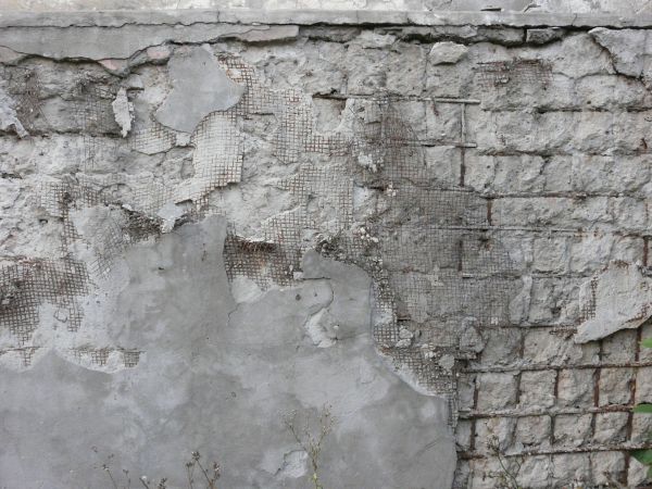
Purpose of Soil Investigation The design of a structure’s foundation requires a thorough understanding of the soil’s chemical and physical properties, as well as its geotechnical parameters. This information is obtained through an investigation of both surface and subsurface soil strata. Boreholes are strategically selected to collect samples that represent various soil conditions relevant to the structure’s foundation. construction management: concrete construction bridge construction:How to become a bridge engineer Figure 1   Sampling The choice of sampling method depends on soil conditions. For soft soils, the ASTM D1587-00 method is recommended, which involves using a thin-walled tube for sample collection. For gravel, large cemented soil particles, and hard soil, ASTM D1586-99 is the preferred method, utilizing a split-barrel sampler to obtain samples. All collected samples should be placed in sealed plastic bags to prevent moisture...

why do we use cranked rebar at rebar overlapping?

Image
 Cranked bars are produced by slightly bending the reinforcement bar before the overlapping zone then straightening it at the overlapping zone, as shown in figure no:1. The main purpose of this practice is to reduce the congestion of reinforcement at the overlapping zone for structure members with a high amount of reinforcement. The use of crank bars will give flexibility in fixing and arranging reinforcement to reduce the congestion, which helps create a larger space between reinforcement rebars. The spacing between reinforcement rebars should be sufficient to allow smooth concrete placement. Small spacing of reinforcement rebar will work as a screen that will enable the concrete paste to pass through it and stop aggregate, which results in concrete segregation. Therefore, cranked rebars can be used to slightly reduce the congestion of reinforcement rebars and increase the spacing between rebars. Figure no:1

why do we stagger reinforcement overlapping?

Image
First, we should know that steel rebar comes in standard length such as 12m. using very long reinforcement is impractical because it will result in difficulties in handling reinforcement by steel fabricators. Also, longer rebar is heavier and difficult to lift and move. So for a long structure such as a slab, we require a reinforcement length that is more than the standard reinforcement. We can't use a single piece of rebar for a specific length for such a structure, so we use two or more steel rebars to cover the entire length of the structure. Figure no:1 The zone of overlapping between reinforcement will be considered as a weak zone. Therefore, it is a good practice to stagger the reinforcement overlapping. Staggering is done by overlapping the reinforcement at a different location. Staggering reinforcement overlapping will reduce the number of rebars overlapped at the same point, which will be beneficial in two ways. Firstly, it will reduce the discontinuity of rebar at the s...

why do we overlap steel rebars??

Image
 First, we should know that steel rebar comes in standard length such as 12m. using very long reinforcement is impractical because it will result in difficulties in handling reinforcement by steel fabricators. Also, longer rebar is heavier and difficult to lift and move. So for a long structure such as a slab, we require a reinforcement length that is more than the standard reinforcement. We can't use a single piece of rebar for a specific length for such a structure, so we use two or more steel rebars to cover the entire length of the structure. Clearly, the point of joining these rebars is critical and weak. So, for this reason, and to prevent structure failure at this point, we overlap the reinforcement to ensure that there is sufficient length to transfer stresses at this point, which prevent: tension, pull-out, and shear failure at the location of joining the rebars. Figure no:1

Finger expansion joint

Image
  Expansion joints are an important component of bridges. The expansion joints are installed in bridges to accommodate the elongation and shortening of the structure due to various causes such as temperature changes. The increase of ambient temperature will increase the bridge deck length. In this case, the expansion joint will absorb the movement of the deck. But if there is no expansion joint, the elongation of the bridge deck will exert high stress on the bridge support and bridge deck, which can result in cracks in concrete and affecting structure integrity. There are various types of expansion joints. The selection of expansion joint will mainly depend on the anticipated movement of the deck. Finger expansion joints can accommodate large movements up to 1000 mm.  Figure 1 The finger expansion joint is composed of the finger's plate, waterproofing membrane, and anchors. The waterproofing membrane will form a channel to drain the water away from the bridge structure. Finger...

shear key

Image
The purpose of the shear key is to improve the bonding between concrete surfaces. The shear key is usually made at the construction joint location to enhance the adhesion between the old and new casted concrete. Construction joint is considered a weak point because the concrete is not casted at one time, in large structures where the concrete can not be casted for some members at one time, such as a slab. We usually divide the slab and cast it at many stages. The large quantities of concrete will make it impossible to cast the slab at one time. Therefore, the casting will be done in several stages. The location of the construction joint should be selected carefully. Construction joint shall be made at the location of minimum shear and moment.  The bonding between old and new concrete can be improved by roughening the old concrete and forming a shear key on the concrete surface while the concrete is still plastic. The shear key can be formed by pressing timber into the concrete surf...

Fiber Reinforced polymer for strengthening of reinforced concrete

Image
 Fiber-reinforced plastic (FRP) is a new technique to strengthen structures. Fiber-reinforced plastic has various types, such as a carbon-fiber-reinforced polymer (CFRP), glass fiber reinforced plastic (GFRP), and aramid fiber-reinforced polymer (AFRP).  The below table shows the mechanical properties of different fiber types.     Table 1 we can notice that carbon fiber reinforced polymer possesses better properties compared to other types. For example, the tensile strength of CFRP extra-high strength can reach 6200 MPA compared to a maximum tensile strength of 4135 MPA of other fiber types.   The FRP has various uses such as: Improved seismic performance of masonry walls Replacing missing steel reinforcement Increasing the strength and ductility of columns Increasing the loading capacity of structural elements Correcting structural design and/or construction defects Increasing resistance to seismic movement Improving service life and durability ...

Prestressing strand manufacturing

Image
  Prestressing strands is high tensile strength steel. The tensile strength of prestressing strands can reach up to 1860 Mpa. the process of manufacturing prestressing steel differs significantly from the conventional reinforcement.  Figure 1 The process of manufacturing strands will begin by de-scaling the raw material (wire rod). The purpose of de-scaling is to remove the iron oxides (mill scale) from the surface of the wire rod. after removing the mill scale, the wire rod's surface is coated with a textured coating to enhance the adherence of lubricants to the raw material surface. The most commonly used coating is zinc phosphate.  Figure 2 The wire rod then passed through a series of dies. The process of reducing the wire rod diameter is known as cold-drawing. In this process, the wire rod is drawn through a die with the required diameter. To prevent the wearing of dies, the wire rod will be drawn through a lubricant box. the lubricant will coat the wire with a thin l...

Prestressing stands debonding

Image
  Prestressing bridge concrete beams contributes to resisting the tensile stresses caused by the traffic loads and the beam's weight. Stressing concrete has various benefits, such as increasing concrete members' capacity, reducing the concrete member section, and increasing the span lengths for structures such as bridges and buildings. However,  The stressing of bridge beam ends can result in unwanted cracks. Therefore AASHTO calling for debonding a specific portion of strands at the beam end to minimize the stresses and reduce cracks. Figure 1 Debonding is achieved by wrapping the strands at the end of the beam with plastic. Wrapping the strand with plastic wrapping will prevent the strands from bonding with concrete, thus avoid transferring unwanted stress to the beam end. As a result, the unwanted cracks will be prevented by reducing the stress levels at the end of the beam.  

Conjugate beam Problem no:6

Image
  Example 5: determine the force F, so the displacement at C will be zero assuming EI constant over the beam length? Figure 1 The first step is to draw the M/EI diagram for the real beam. The conjugate beam will be loaded with M/EI diagram for the real beam. The pin at A will stay the same for the conjugate beam while the internal roller at B will change to an internal pin for the conjugate beam. The free end at point C will become a fixed end. So the conjugate beam will be as shown in figure no:2.  Figure 2 To draw M/EI, we need to determine A and B's reaction for the real beam. Figure 3 So the shear and moment diagram will be as shown in figure no:4. Figure 4 Now, we will take section B-C. to determine FB using the equilibrium equation(MC=0). Figure 5 Now, we will take section A-B. to determine FB using the equilibrium equation. The FB computed from section A-B will be equaled to Fb calculated from section B-C to determine F related to P. To calculate a1 and a2, we will use ...

Conjugate beam Problem no:4 (Beam with internal pin, roller and point load )

Image
Example no:4: find the displacement at point C and the slope at point B for the beam shown in figure no:1. Figure 1 The conjugate beam will be, as shown in figure no:2. The pin and roller at A and B will become internal pin. The free ends will become fixed, as shown in figure no:2. We need to determine the M/EI diagram for the real beam, which will be the load in the conjugate beam, to determine the displacement at point c and slope at point B. Figure 2 To draw the moment diagram for the beam, we need to determine the reaction at point A and B, then draw the shear diagram and the moment diagram. Using the equilibrium equations: Figure 3 The shear and moment diagram will be, as shown in figure no:4. Figure 4 The conjugate beam will be loaded, as shown in figure no:5. Figure 5 To determine the displacement at point C, we need to determine the moment in the conjugate beam at point C. to determine the moment at point C, we will take section A-B to determine the force at B. Figure 6 Now we...

Binding wire for steel reinforcement

Image
  Binding wires are used to tie steel bars together. These wires are playing a significant role in maintaining the reinforcement stability and rigidity. Wires are used to tie the steel bars at intersections points. By tying the steel bars together, we ensure that the steel bars will not move from their locations during construction or during the time of concreting. In slabs, binding wires are used to tie longitudinal and transverse bars together. In columns, it is used to tie vertical bars with stirrups.   Figure 1 There are various types of binding wires such as  Black annealed baling wire, Stainless Steel Binding Wire, and PVC coated binding wires.  Black annealed baling wire used to tie black steel. The popular size for black wire ranges from 16 to 22 gauges. Stainless steel binding wires are used to bind stainless steel reinforcement. Stainless steel reinforcement is used in a harsh environment where the black steel gets rusted quickly. Therefore, stainless ...

Conjugate beam Problem no:3 (Determining the distance a)

Image
  Determine the distance "a" so the displacement at the edge of the beam equals the displacement at the center of the beam? Figure 1 The conjugate beam will be, as shown in figure no:2. The pin and roller at A and B will become internal pin. The free ends will become fixed, as shown in figure no:2. We need to determine the M/EI diagram for the real beam, which will be the load in the conjugate beam, so we can determine the distance “a” that will cause an equal displacement at the end and center of the beam.  Figure 2 Using the equilibrium equations, we will determine the reaction at point A and point B. Figure 3 After determining the reactions at support A and B, we can now draw the shear and moment diagram. The M/EI will be the load on the conjugate beam as shown in figure no:4 and 5. Figure 4 Figure 5 Now we need to equal the moment at the end beam and the center of the beam. we assume the distance between A and B equals L1 and L1=L-2*a. To simplify the solution, we will ta...

Videos from My Youtube channel

Popular posts from this blog

Pile cap

Binding wire for steel reinforcement

Casing for piles

Repairing of concrete bulging

Bridge Diaphragm

Non-Working Pile Testing and Static Compression Load Test

Lateral support and skin reinforcement for reinforced beam

Equivalent Single Axle Load (ESAL) in Pavement Design

Driven piles

Flakiness Index and Elongation Index of Coarse Aggregates