


Working piles (cast in situ piles)
Various Methods Used in Constructing
Cast In-Situ Piles
The general concept of cast in-situ
pile construction remains the same across various methods, with minor
differences. Bored pile diameters typically range from 600 mm to 3000 mm, with
depths reaching up to 70 m. This provides designers with significant
flexibility to customize foundation designs according to site conditions and
optimize costs for an economical solution.
Casing
Installation
The depth of casing varies based on
site conditions and soil properties. In the presence of loose soil, the casing
length should be increased. The use of bentonite can help prevent soil
collapse, reducing the required casing length.
The primary function of the casing
is to prevent soil collapse in loose soil conditions or when soil-supporting
liquids are absent. It also allows land surveyors to verify pile locations and
provides guidance for drilling machines. Casing installation involves drilling
a shallow hole with the same diameter as the casing to facilitate insertion
using a vibration hammer.

The casing diameter should be slightly larger than the pile diameter and free from distortion. For long casings, joints must be properly and smoothly welded. Before casing installation, any residual or encrusted concrete must be removed.\
Setting Out
The casing location should be verified by a land surveyor and compared with the pile coordinates. The casing must be within 75 mm of the original pile location. If not, it must be lifted and repositioned.
Boring
Boring should commence only after verifying the casing location. Drilling is performed using a rotary rig or other suitable equipment. The drilled shaft depth must be at least equal to the pile depth, calculated as follows
Depth of Drilling = Casing Top Level - Toe Level

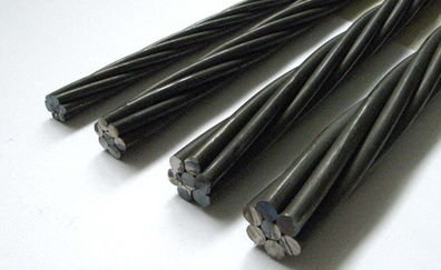
Steel Cage Fabrication and LoweringThe steel cage should be fabricated as per the design drawings. The steel must be free from rust, and any rust formation should be thoroughly removed. Concrete cover blocks should be used to maintain the required cover, with the concrete strength of the cover blocks matching that of the pile to prevent spalling or deterioration.
PVC sleeves can be used to confine steel projecting above the cut-off level, facilitating easier concrete breaking in later stages. Overlap length and location must comply with the design specifications.

To minimize distortion, two cranes
should be used when lifting the steel cage. The borehole should also be cleaned
before lowering the cage. The cage will be hooked to the casing, and the top
steel level must be checked by a land surveyor.


Pile
Casting
To avoid soil sedimentation, the time between lowering the steel cage and pile casting should be minimized. Tremie pipes must be used for pile concreting and should be free from residual concrete, oil, grease, or any contaminants. The tremie length should be at least equal to the borehole depth. During casting, the tremie must remain embedded in the concrete at all times to prevent segregation or contamination.

Casing
Removal
The casing should be removed while
the concrete is still fresh. Delayed removal can cause adverse effects, such as
concrete cracks or adhesion between the concrete and the casing, leading to
potential pile extraction during casing removal. If casing removal is
significantly delayed, it is advisable to leave the casing in place and conduct
a static compression test to verify pile capacity.
Use
of Stabilizing Liquids
Property
|
At
time of slurry
Introduction
|
In
hole at time of
concreting
|
Test
method
|
Density
|
995-1018kg/m3
(Fresh
water)
|
1000-1018kg/m3
(Fresh
water)
|
Mud
Balance
(API
13B-sec1)
|
Viscosity
(minimum)
|
45sec/.95liter
|
45sec/.95liter
|
Marshal
funnel
|
PH
|
8-10
|
8-10
|
pH
paper/pH meter
(API
13B-Sec6)
|
MAX
sand content
(1%
by volume)
|
1
|
1
|
Sand
Screen set
(API
13B-Sec4)
|
Limitations
of Cast In-Situ Piles
Minimum
Clearance
Adequate clearance must be
maintained between adjacent cast in-situ piles during construction. The minimum
distance should be at least three times the pile diameter. If a smaller
clearance is unavoidable, one pile should be bored and cast first, and the
adjacent pile should only be drilled and cast after allowing sufficient curing
time (typically seven days).

Tremie
Pipe Considerations
The internal diameter of the tremie
pipe should be at least 150 mm for a concrete mix with a maximum aggregate size
of 20 mm. This ensures a smooth concrete flow. For small-diameter piles, the
tremie pipe size must be selected carefully to avoid difficulties during
insertion. Additionally, any attachments to the steel cage, such as sonic tubes,
must be considered during planning.


Comments
Post a Comment