


Hardware for post-tensioning
1.
Anchorage
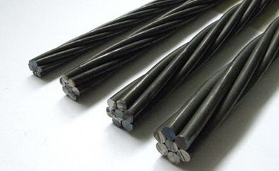
Anchorage is a device used to secure
prestressing steel and is installed at the edge of a concrete member or the
prestressing end. There are two main types of anchorage:
- Dead-end anchorage:
Embedded within the concrete, providing a fixed termination point for the
prestressing tendons.
- Live-end anchorage:
Positioned at the edge of the concrete member, where prestressing occurs.
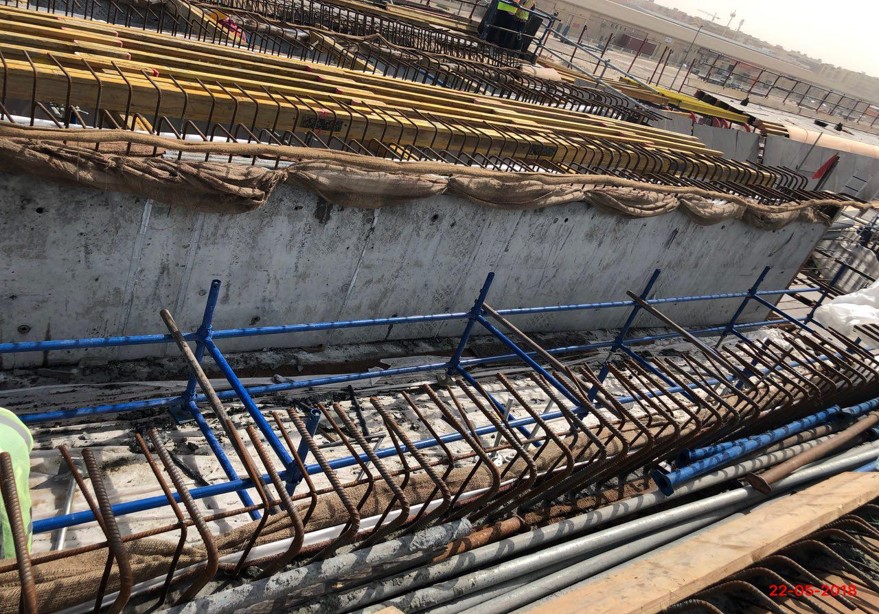
The jacking operation is done at the live end anchorage and the applied load is transferred to concrete members after the completion of tendon jacking.
Anchorage device consists of:
 | ||
| anchorage device
A. Bearing plate: Typically
round or rectangular, its primary function is to transfer the prestressing
force from the tendons to the concrete.
B. Wedging plate: This
component holds the strands in place. The strands transfer their force to the
wedging plate, which in turn transmits it to the bearing plate.
  Dead anchorage 2.PT ducts serve as protective conduits through which prestressing strands are installed after the concrete has attained sufficient strength.
Key requirements for PT ducts:
 |

3. Couplers: Couplers are crucial components in
post-tensioning systems, particularly in bridge construction, where continuous
tendons span multiple girders. Due to frictional losses during stressing,
couplers are used to optimize prestressing efficiency.
Key considerations:
- 50% of tendons
should be coupled within the same region to maintain structural balance.
- According to AASHTO (5.10.3.5), coupling all
tendons at a single section can reduce the concrete section's strength and
increase creep, which must be carefully managed in design.


4. Grout
Inlets, Outlets, Valves, and Grout Caps
- Grout inlets:
Installed at high points to monitor grout flow quality during injection.
- Grout outlets:
Placed at low points to facilitate drainage of water or grout in case of blockage
or process interruption.
- Grout caps:
Fixed onto the bearing plate after stressing and strand cutting. They
prevent grout leakage from the wedge plate during the grouting process.

 |
| grout cap |
 |
| grout inlet Video for article |


Comments
Post a Comment