


Example 2: design of rectangular beam
design rectangular sections for the beams, loads, and ρ values shown. Beam weights are not included
in the loads shown. Show sketches of cross sections, including bar sizes, arrangement, and spacing. Assume concrete weighs 150 lb/ft3 , fy= 60,000 psi, and fc'= 4000 psi, unless given otherwise.


in the loads shown. Show sketches of cross sections, including bar sizes, arrangement, and spacing. Assume concrete weighs 150 lb/ft3 , fy= 60,000 psi, and fc'= 4000 psi, unless given otherwise.

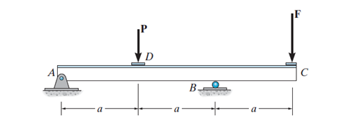
Figure 1
first, we will calculate the ultimate load, we have point live load and distributed dead load, therefore we will take each load separately
ultimate live load=1.6*PL=1.6*20=32k
assuming the weight of beam=0.40k/ft
dead load=2+0.4=2.4 k/ft
ultimate dead load=1.2*2.4=2.88k/ft
the ultimate moment will be at the mid of beam= 50.56*12-2.88*12*6=399.36k-ft
Mu=Ф*Mn=Ф*Asfy(d-a/2)
Mu/(b*d^2)=Ф*ρ*fy(1-fy*ρ/1.7*fc')
ρ=0.18*4,000/60,000=0.012
bd^2=Mu/(Ф*ρ*fy(1-fy*ρ/1.7*fc') assuming Ф=0.90
Mu=399.36K-ft=4,792,320lb-in
bd^2=4,792,320/(0.9*.012*60,000*(1-60,000*0.012/1.7*4000))=8,271.34
bd= 12x27
14x24
using 14*28 as beam dimension (bxh)
checking beam weight=14*28*150/144=0.40k/ft ok
As=ρ*b*d=0.012*14*24=4.032in2
using 3#11=3*1.56=4.68 in2
checking for Ф=0.9 or no
(εt+0.003)/(d)=0.003/c
C=a/β1
β1=0.85 for fc'=4000 psi or less
a=Asfy/(0.85*fc'*b)
a=4.68*60,000/(0.85*4000*14)=5.9in
C=a/β1=5.9/0.85=6.94in
εt=0.003*(24.3)/C-0.003=0.0075>0.005 so section is tension control Ф=0.9 is ok
checking for ρmin
As,min=(3√fc'/fy)*bw*d and not less than 200bw*d/fy
As,min=3*√4000*14*24.3/60,000 and not less than 200*24.3*14/60,000
As,min=1.075 in2 and not less than 1.134in2 ok, our As is larger than the minimum
checking Ф*Mn>Mu
Ф*Mn=0.9*4.68*60,000(d-a/2)
Ф*Mn=0.9*4.68*60,000(24-5.9/2)=5,319,756> Mu


Comments
Post a Comment