


Shear and Moment Diagrams for a Frame
Frames are made from connecting several members together. The procedure for drawing shear and moment diagrams for a frame is similar to drawing shear and moment diagram for a beam. The reaction at support should be determined. Then the internal forces should be determined at the end of members using the method of section. Provided all loadings are resolved into components acting parallel and perpendicular to the member’s axis, the shear and moment diagrams for each member can then be drawn as described previously.
You can select sign convention for moment diagram. We can draw a positive moment diagram on the tension side of the frame. Here we will draw the positive moment diagram on the compression side of the frame.
Examples


You can select sign convention for moment diagram. We can draw a positive moment diagram on the tension side of the frame. Here we will draw the positive moment diagram on the compression side of the frame.
Examples
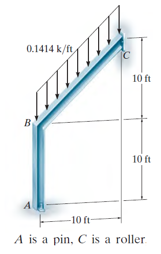
Figure 1

Figure 2(reactions)
Figure 3(shear and moment diagram)
Figure 4
Figure 5(shear and moment diagram)


Comments
Post a Comment