Video from my YouTube channel

Subscribe to My You tube channel

Conjugate beam Problem no:5

Example 5: determine the displacement at C and the slope at point B for the beam shown in figure no: 1 considering EI a constant?

Figure 1


The support at A for this beam will allow the rotation but no movement, so it is considered a pin, and it will stay the same in the conjugate beam. While the support at B will allow the movement in horizontal direction and rotation, it will be similar to the roller, and it will stay the same in the conjugate beam. So the real beam will be as in figure no:2. And the conjugate beam will be as shown in figure no:3.

Figure 2

Figure 3


To determine the displacement at point C and the slope at B, we need to determine the moment at point C and the shear at point B in the conjugate beam. The conjugate beam will be loaded with M/EI of the real beam, so we need to draw M/EI for the real beam. To draw the M/EI diagram, we need to determine the reaction at point A and point B.

From the symmetry we can know that the reaction FA=FB=P. so the shear moment diagram will be as shown in the figure no:4.

Figure 4


So the conjugate beam will be loaded as shown in the figure no:5. 
Figure 5


From the symmetry the reaction FA=FB. So


To determine the displacement at point C, we need to determine the moment, we will take the section A-C. so using the equilibrium equations


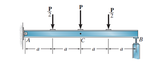




Figure 6

Figure 7


Comments

Videos from My Youtube channel

Popular posts from this blog

Pile cap

Bridge Diaphragm

Rebar Splicing and Overlapping — ACI 318-19 Requirements Explained

Analysis of T Beams

Non-Working Pile Testing and Static Compression Load Test

shear key

Repairing of concrete bulging

Flexible Pavement Layers and Their Components

Pressure Reducing (or Pressure Breaking) Valves

ACI Reinforcement Limits Explained: Minimum and Maximum Steel Area for Concrete Columns