Posts

Showing posts with the label Soil

Subscribe to My You tube channel

Los Angeles abrasion test

Image
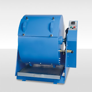
Los Angeles abrasion test conducted to measure the resistance of aggregates to deterioration by impact, abrasion and grinding. The deterioration due to impact, abrasion, and grinding determined by measuring the percentage of wear due to relative rubbing action between aggregates and steel balls inside a drum rotating at a specific speed. the test apparatus includes balance, sieves (80, 63, 50, 40, 25, 20, 12.5, 10, 6.3, 4.75 (as per gradation of aggregate) and 1.7 mm), Los Angeles abrasion machine and abrasion charges.   Figure 1 Figure 2 Test procedure ·         the grade of aggregates will be determined by the sieving of the aggregate sample. The table no:1 shows the different grades of aggregate according to gradation. Table 1 ·         The test sample shall be clean and dried in an oven at 105 to 110 c˚. The grading of the aggregate shall conform to one of the grading shown in table no:1. The grading of aggregates shall be similar to the g

California bearing ratio test

Image
  California bearing ratio test gives an indication of the shear strength of a soil. The simplicity of performing this test makes it used widely over the world. There is a vast amount of data to assist with the interpretation of results. CBR is the ratio of the unit force required by a 50 mm standard circular plunger to penetrate a soil sample at 1.25 mm/min to the force required to penetrate a standard material. This ratio will be expressed as a percentage. The ratio usually determined for penetration in the soil of 2.5 mm and 5 mm. When the ratio at 5 mm is consistently higher than that at 2.5 mm, the ratio at 5 mm is used. The table no:1 shows the standard load at the penetration of 2.5mm and 5.0 mm.  Table 1 CBR test apparatus: Loading machine with a capacity of at least 5000 kg and equipped with a movable head or base which enables Plunger of 50 mm dia. To penetrate into the specimen at a rate of 1.25 mm/ minute. Figure 1 Cylindrical mold: Inside dia. 150mm and

cone penetration test

Image
A cone penetration test is used to determine the geotechnical properties of soil. Cone penetration tests become one of the most widely used tests internationally for evaluating the properties of soil. Cone penetration tests can be completed from the ground surface. The size of rig equipment used to test the soil varies from small portable rig to large-truck mounted rig.  Figure 1 The testing rig will push a steel cone about 32 mm in diameter into the soil. The cone steel will be pushed to a depth of 20 m or once it reaches a hard layer of soil. The cone steel will be equipped with a measuring system that measures the tip resistance and sleeve friction. As the rig pushes the cone steel, the soil resistance for different layers is measured and recorded using a sensor at the cone steel tip. As the sensor at the tip recording the resistance force, sensors at the cone steel sleeve will record the friction resistance. Cone steel can be equipped with a pore water transduce

Field density test-sand cone method

Image
Knowing the dry density of soil or pavement is important to evaluate the degree of compaction achieved during the construction process. A field density test is a common test used to determine the field density of the soil or pavement. The principle of field density test is the replacement of soil excavated materials by the sand, the sand density is known so we can calculate the volume of the sand required to fill the hole. By knowing the volume of the hole excavated in soil and the weight of soil, we can calculate the in-situ density. The in-situ density equals the weight of excavated materials divided by the volume of excavated material. Apparatus  Sand pouring cylinder equipment Small sand pouring cylinder equipment: this suitable for fine and medium-grained soil. It consists of a cylinder having a diameter of 100 mm and a length of 380 mm with an inverted funnel at one end and a shutter to open and close for the entry of sand. Also, there will be a metal tray fo

Compensating grouts-Ground improvement

Image
Compensating grouts is a soil stabilizing method. It is used to protect the structures in the vicinity of tunnels under construction. This method used to control the settlement of structures due to the change of soil stress as a result of construction work for tunnels. This method aims to stabilize the structures in the vicinity of tunnels. This method will be used to maintain or re-leveling structures or ground subjected to on-going settlement. In general, compensating grouts will be implemented if engineers determined that the supporting of tunnel excavation is not sufficient to prevent and reduce the settlement to an acceptable level. construction management: concrete construction bridge construction:How to become a bridge engineer The grout will be injected at a level between the tunnel crown and the structures needed to be protected. Generally, the grout is injected from predrilled holes. These holes will be drilled radially from an access shaft, as shown i

Fore-poling (ground improvement for tunnel excavation)

Image
This technique used to improve the ground and limiting the decompression of the crown of the excavation for tunnels. Steel bars (dowels) or steel plates(forepoles) are installed in the upper third or quarter of the excavation. Dowels and forepoles installed ahead of the tunnel excavation from the face periphery. Figure no:1 showing the installation of dowels and forepoles before commencing with further excavation of tunnels to stabilize the soil ahead. Figure 1 construction management: concrete construction bridge construction:How to become a bridge engineer Steel bars or dowels are similar to the one used for rock dowels. Dowels are installed from within the tunnels. Dowels are placed above a lattice girder. Dowels will be positioned at an angle to the direction of excavation, as shown in figure no:2 if the ground is very dense and hard. The dowels will be installed in a predrilled hole. The predrilled hole will be filled with grout before installing the do

Face dowels (ground improvement for tunnel excavation)

Image
Fiberglass dowels are used widely to stabilize the poor ground for excavating tunnels. Face dowels are installed over the cross-section of the tunnel. Fiberglass reinforcement can be used to reinforce the excavated area. Fiberglass dowels installed in predrilled holes then injected with cement mortar. Dowels used to strengthen the face of the tunnel should be made from a material that can be easily excavated. Fiberglass reinforcement can be excavated easily. Using of fiberglass reinforcement will be suitable when TBM or road header used to excavate the tunnel as they can be easily excavated and removed. However, the using of fiberglass dowels for other methods of excavation may pose a risk because fiberglass is a brittle material. The breaking of fiberglass will produce potentially dangerous sharp edges, which may affect the safety of workers. Figure 1 construction management: concrete construction bridge construction:How to become a bridge engineer Steel d

What is water hammer?

Image
Water hammer can be defined as a sudden increase of pressure inside the pipe due to the sudden change of direction or velocity of the liquid flowing inside the pipe. Water hammer can cause the rapture of the pipe and severe damage to the equipment.  construction management: concrete construction bridge construction:How to become a bridge engineer To explain the cause of water hammer, we need to understand that the flowing liquid has two types of energies: Kinetic energy and potential energy. The kinetic energy generated by the velocity of the fluid while the potential energy represented by the liquid pressure. Neglecting the friction inside the pipe, the combination of both energy is constant along the pipe length. A sudden change of liquid velocity will result in changing the kinetic and potential energy. If the velocity decreased, the kinetic energy will decrease. The decrease of kinetic energy will result in an increase of potential energy or in other word, t

Catch basin for stormwater

Image
A catch basin is an inlet to a stormwater drain system with a grate cover. The function of the catch basin is to capture sediments, debris, and associated pollutants. The purpose of the catch basin is to prevent the downstream pipes from being clogged with sediments or other pollutants and to reduce the amount of pollutants discharged to rivers and streams. The catch basin captures the pollutants by settling or infiltration mechanisms. In the first mechanism, pollutants settle at the bottom of the catch basin sump. In the second mechanism, a leaching basin is used. The leaching basin is similar to the standard basin. The bottom of the leaching basin is made from loose aggregates, through which stormwater flow and infiltrate into the soil below. The leaching basin should not be used if there a possibility of ground contamination. The figure no: 1 showing standard catch basin and figure no: 2 showing leaching catch basin. Catch basins are located at low points and otherwise spaced

Tack Coat

Image
Tack coat is the application of asphalt binder by spraying over the old asphalt layer prior to placing the new asphalt layer. Tack coat will act like a glue to provide a bond between asphalt layers. The absence of a tack coat will result in a weak bonding of asphalt layers. The absence or poor application of tack coat may cause slippage cracks, fatigue cracks, and formation of potholes. The materials used for the tack coat is emulsified asphalt, performance grade asphalt, and cutbacks. The using of emulsified asphalt is more common and preferred over cutbacks because it is providing a better bonding strength. construction management: concrete construction bridge construction:How to become a bridge engineer The absence or poor bonding between asphalt layers will reduce the service life of the pavement. Roffe and chaigon suggested that no bonding between the asphalt layer will reduce the service life of the pavement by 60%. The most common tack coat materials

Prime coat

Image
A prime coat is the application of low viscosity bituminous materials to the absorptive surface to penetrate, bond, and stabilize the existing surface before laying the asphalt mix. Usually, the prime coat is applied above the aggregate base coarse or granular bases that will receive the asphalt layer. While the tack coat is applied between two layers of asphalt. Tack coat is a very light application of bituminous materials to ensure proper bonding between two binder layers. Figure 1 construction management: concrete construction bridge construction:How to become a bridge engineer the benefits of using prime coat are as follow: · Prime coat will penetrate and fill the voids of the granular base course. Also, it will coat and bond the mineral particles in the base course to produce a tough and tight surface to receive the binder layer. · Prime coat will waterproof the granular base course, which provides protection from the wet weat

Ground improvement and stabilization techniques-Ground reinforcement

Image
Ground improvement and stabilization can be achieved by different methods such as ground freezing , lowering the water table , ground grouting , and ground reinforcement. Three distinct methods used to reinforce ground. Rock dowels: these reinforcing elements consist of dowel, faceplate, and nut, as shown in figure 1. those elements are installed without tension. The materials of dowel will vary depends on the purpose of use, whether it is temporary or permanent. Deformed bar, glass fiber, and plastic can be used. The dowel of the reinforcing element usually embedded in mortar filled or grouted pipe, also resin capsules are used. Rock dowels can be used to stabilize the ground or hard rock. Dowels are placed at a discrete location to prevent unstable parts of ground or hard rock from falling during excavation. Figure 1 construction management: concrete construction bridge construction:How to become a bridge engineer Another form of rock dowels is infl

Ground improvement and stabilization techniques-Ground grouting

Image
Grouting is the process of injecting grout materials into the ground. The purpose of ground grouting  reduces the permeability of the ground. Improve the strength and stabilize the soil. The grouting can be performed from the ground surface or from an adjacent shaft in the case of excavation for a tunnel or from within the excavation itself. Grouting can be used to stabilize an existing structure foundation that likely to be impacted by the excavation. construction management: concrete construction bridge construction:How to become a bridge engineer For tunnel grouting. The holes for injecting grouting are drilled at an acute angle to the axis of the tunnel to form overlapping cones of treated ground. Also, it can be drilled from the face of the tunnel. For TBM method the holes can be drilled forward from the rear of the machine to avoid disturbing the cutter wheel. Also, grouting can be performed toward the face of the tunnel and radially using the shield

Ground improvement and stabilization techniques-Lowering of the groundwater table

Image
Lowering the groundwater table will significantly improve the soil properties. Reducing of the groundwater table is a time-limited process and not always possible. Under running steams. Where the settlement could affect an important area adversely such as inside cities groundwater lowering should not be allowed. Also, it should not be permitted if the groundwater lowering could impact the flora and existing water supply aquifers. Groundwater lowering methods will required arrangement for storing the water. In some cases, it is necessary to treat the water before discharge it.  In permeable strata where the permeability, k, exceeds about 10–3 cm/s, or where an aquifer can be dewatered below less permeable strata, the level of the water table over a wide area can be drawn down by pumping from boreholes and deep wells. These processes are widely used in open excavations and are also suited to cut-and-cover tunnels and shallow bored tunnel. Figure 1 construction management: co

Popular posts from this blog

Bar Bending schedule (BBS)

Binding wire for steel reinforcement

Pile cap

Repairing of concrete bulging

stress-strain diagram for aluminium alloy and rubber

Bridge Diaphragm

Non-working piles

Nominal maximum size of coarse aggregate

shear key

The reasons behind the trimming of pile head

My photo
Mohammad
My name is Mohammad Hamdan, and I am a Civil/bridge Engineer with extensive professional background and experience in the field of construction. I have 10+ years of experience in the construction field. During my professional career, my emphasis has been placed on structural projects, mainly bridges, infrastructure and roads. Reading and practicing the design of structures is my passion.i was lucky to be a part of a big team that executed major highway interchanges. I believe in spreading the knowledge, thus, i compose these courses to share my experience and knowledge. My course focuses on the practical side of construction field. On other word, i am sharing some of what new engineers need to know about construction field. Beside working on construction field, i love writing some articles on my website ( curious civil engineer) Moreover, i wrote some engineering papers, you can check them  by searching my name on Google (Mohammad mamon Hamdan)