Posts

Showing posts with the label concrete

Subscribe to My You tube channel

Binding wire for steel reinforcement

Image
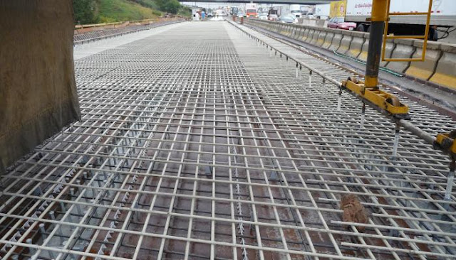
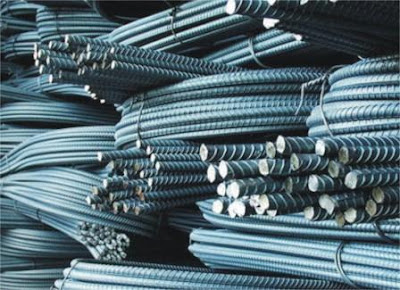
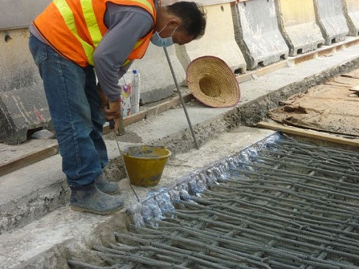
  Binding wires are used to tie steel bars together. These wires are playing a significant role in maintaining the reinforcement stability and rigidity. Wires are used to tie the steel bars at intersections points. By tying the steel bars together, we ensure that the steel bars will not move from their locations during construction or during the time of concreting. In slabs, binding wires are used to tie longitudinal and transverse bars together. In columns, it is used to tie vertical bars with stirrups.   Figure 1 There are various types of binding wires such as  Black annealed baling wire, Stainless Steel Binding Wire, and PVC coated binding wires.  Black annealed baling wire used to tie black steel. The popular size for black wire ranges from 16 to 22 gauges. Stainless steel binding wires are used to bind stainless steel reinforcement. Stainless steel reinforcement is used in a harsh environment where the black steel gets rusted quickly. Therefore, stainless steel reinforcement is u

Conjugate beam Problem no:3 (Determining the distance a)

Image
  Determine the distance "a" so the displacement at the edge of the beam equals the displacement at the center of the beam? Figure 1 The conjugate beam will be, as shown in figure no:2. The pin and roller at A and B will become internal pin. The free ends will become fixed, as shown in figure no:2. We need to determine the M/EI diagram for the real beam, which will be the load in the conjugate beam, so we can determine the distance “a” that will cause an equal displacement at the end and center of the beam.  Figure 2 Using the equilibrium equations, we will determine the reaction at point A and point B. Figure 3 After determining the reactions at support A and B, we can now draw the shear and moment diagram. The M/EI will be the load on the conjugate beam as shown in figure no:4 and 5. Figure 4 Figure 5 Now we need to equal the moment at the end beam and the center of the beam. we assume the distance between A and B equals L1 and L1=L-2*a. To simplify the solution, we will ta

Glass fiber-reinforced polymer

Image
  Glass fiber-reinforced polymer (GFRP) reinforcement has emerged as a new opponent to conventional reinforcement. The GFRP owns a higher tensile strength, non-corrosive reinforcement, lighter weight, and higher strength-weight ratio. The corrosion of reinforcement can severely damage the structure by causing the concrete to cracks or spall. The Maintainance of damaged structures can significantly be costly. The GFRP is a non-corrosive reinforcement. Therefore, the use of GFRP can eliminate the deterioration of structure due to reinforcement corrosion. The use of GFRP has increased recently for many applications such as bridge deck, pavement, walls, and other applications. However, the use of GFRP is limited due to the lack of information about the long-term performance of GFRP. Figure 1 GRFP bars have many advantages, such as tensile strength. The tensile strength of GRFP bars is higher than the conventional reinforcement. Table no:1 shows the mechanical properties of GRFP bars. We ca

TMT steel bar

Image
  TMT bars are thermally mechanically treated steel bars with high strength and good mechanical properties compared to mild steel bars. TMT bar is a new enhanced version of mild steel bars. The treatment process of TMT bars includes 3 stages: quenching, self tempering, and atmospheric cooling. The quality of produced TMT bars depends on the quality of raw materials, quality of rolling mill, and quality of quenching and tempering process.  Figure 1 The process of manufacturing steel is divided into two stages. The first stage is molten iron production. In this stage, iron-sand and coal are heated in a multi-hearth furnace—heating the raw materials done in stages. First, the furnace pre-heat the material to reduce the volatile matter present in coal from 44% to 9%. There are 12 hearths in each furnace. The mixture temperature will be increased gradually through these hearths. Finally, the temperature will be adjusted to 620 C.  Figure 1 The output after removal of the impurities introduc

Conjugate beam Problem no:1 (beam with pin and internal roller)

Image
 Problem no:1, Determine the slope and displacement for the following beam at point C? Figure 1 In this example, the pin support will stay the same in the conjugate beam. While the roller will change to hinge and the free end to a fixed support. So the conjugate beam will be the same as shown in figure no:2. Figure 2 Now we need to determine the moment diagram for the real beam.  First step is to determine the force at support A and B by the use of equilibrium equations: Figure 3 Now we can draw the moment diagram for the real beam. To draw the moment diagram, we can draw the shear first, and the moment diagram will be the area of shear. The moment diagram for the real beam will be, as shown in figure no:4. Figure 4 After drawing the shear and moment diagram, our conjugate beam will be loaded with the M/EI diagram of the real beam, as shown in figure no:5. Figure 5 now to determine slope and displacement at c we need to calculate the shear moment at c by the use of equilibrium equatio

Ductility of reinforcing steel

Image
 Ductility is an important property of steel reinforcement. Ductility is the ability of the material to undergo plastic deformation before failure. The ductility of reinforcement is related to the elongation property. The ductility of reinforcement ensures safer and durable structures. Material that undergoes little or no plastic deformation is known as a brittle material. Brittle reinforcement can cause sudden structure failure because it doesn't undergo any plastic deformation before failure.  Figure 1 The ductility factor for reinforcement can be computed using the following equation: µ=ϵu/ϵy where, µ is the ductility factor ϵu is the ultimate strain ϵy is the yield strain In figure no:1-a, we can see the stress-strain curve for mild steel. The mild steel has well-defined yield stress and strain, as shown in the stress-strain curve. The reinforcing bar can recover all the elongation if the applied stress is lesser than the yield stress. This portion of the curve is known as the

Useful Engineering Courses

 Construction management: Road construction course This course is designed to expand your practical side of engineering knowledge. This course is concentrating on the construction of roads. Here you will learn how the road is constructed. The construction stages such as protection of existing services, clearing the area, future utilities, preparing the road subgrade, then placing different pavement layers such as sub-base, base course, and asphaltic courses. We will also discuss the types of asphaltic course and the common defects of asphaltic pavement, such as permanent deformation, fatigue cracking, and low-temperature cracking. Also, I will show a typical cross-section of road and road profiles and many other subjects. Enroll from here  Pile foundation design This course will discuss the design of pile foundations. We will learn the methods of calculating the pile bearing capacity. The bearing capacity for a pile consists of skin and end bearing resistance. Here you will understand

corrosion protection of reinforcement by galvanization

Image
 Corrosion of steel reinforcement is problematic and posing a threat to reinforced concrete structures. Severe corrosion of reinforcement can result in concrete spalling and damaging structure integrity. Various factors can affect the rate of reinforcement corrosions. The environment is one of these factors. For example, the rate of reinforcement corrosion will accelerate for structures submerged in seawater compared to structures built above the ground—concrete properties playing an important role in reducing the rate of reinforcement corrosion. Concrete with low permeability will reduce the ingress of chemicals that cause the corrosion of reinforcement, which can effectively slow the corrosion of reinforcement. The concrete cover is another factor that can effectively slow reinforcement corrosion. Usually, a higher concrete cover is used for members of the structure in contact with groundwater or soil. Figure 1 In a severe environment, galvanized reinforcement can be used to reduce

Foundation of structures

Image
  Foundations are an essential part of any structure. Structures will not be able to withstand imposed loads, and it will fail in case of using the wrong foundation type or foundation with a smaller size. Determining the type of foundations will be based on a soil investigation study. Soil investigation will determine the soil bearing capacity and the other characteristics of the soil. Loads transferred from the structure is playing an important role in determining the type and size of foundations. For small structures, shallow foundations will be sufficient to transfer the load to the soil. On the other hand, huge structures required deep foundations to transfer the loads to the soil without causing large settlement or structure failure.  Figure 1 The method of construction and the mechanism of distributing the loads are different in shallow and deep foundations. Shallow foundations are composed mainly of footing. The shape of the footing can vary. It can be the square, rectangular, o

Cofferdam structures

Image
  Cofferdams are temporary structures used as a barrier to keep out the water and soil during the construction of a permanent structure such as a foundation in a maritime environment. The loads imposed on cofferdams structure includes hydrostatic forces of the water and dynamic forces due to waves and currents. The construction of cofferdams is a tough job since it is usually constructed offshore and in severe weather conditions. Therefore, the tolerance of construction may deviate from the design due to construction conditions, and cofferdams elements may deform significantly during cofferdam construction.  Figure 1 For a typical cofferdam, the construction sequence will be as follow. The construction of the cofferdam will begin with the preparation of the cofferdam area. The soil and sediments will be removed, and the area will be leveled.  The temporary support piles will be driven, and temporary supporting frames will be erected on support piles.   Figure 2 Drive the sheet pile to

Repairing of concrete cracks

Image
The methods of repairing concrete cracks are dependant on crack types. We have two types of cracks: dead and live crack. The concrete cracks that are stagnant and not growing, known as dead cracks. While if the cracks growing in size, it is known as live cracks. The repairing of dead cracks is easier. Once the dead cracks are appropriately repaired, there is a lower chance that the concrete will crack again. Concrete cracks can reduce the durability of the structure. Cracks will work as a passage of harmful chemicals such as chloride. The ingress of chloride will accelerate the corrosion of reinforcement, and this can cause concrete spalling and excessive cracking of concrete.   Figure 1  Dead cracks are caused by a previous event such as concrete shrinkage or accidental overloading of the structure. Cracks wider than 1 mm can be sealed by filling them with cement grout. For finer cracks or those in the soffit or vertical surfaces, Polymer can be used to seal them. Epoxy resin or polye

Concrete bonding agent

Image
  Concrete bonding agent used for bonding fresh concrete to existing hardened concrete. the bonding agents can be used for existing horizontal or vertical concrete surfaces where the fresh concrete will be supported by formworks. the bonding agent can be used at construction joint locations to ensure better adhesion between old and new concrete. in large structures such as bridge deck. the casting of the whole deck at one time is difficult and not practical. therefore, the deck divided into areas and each area casted separately.  Figure 1 before applying the bonding agent, the existing concrete surface should be cleaned properly. all grease, loose concrete, plaster, oil, or any other dirt should be removed. furthermore, the surface of the concrete should be roughened by scrabbling or grit blasting. The mixing and applying of bonding should be as per the manufacturer. the component of the bonding agent should be mixed properly. the bonding agent should be applied thoroughly on the exist

Fatigue failure

Image
Fatigue is an interesting phenomenon. Fatigue is a condition in which the material cracks and fails due to cyclic loading under the ultimate strength of the material. In fatigue, the materials are not loaded to their limit. However, the materials fail, and the reason behind failure is the repeated cycles of loads. Fatigue often occurs suddenly, and it can result in catastrophic consequences.    Figure 1 When a material is loaded, a crack will be initiated or nucleated in the materials. The continuous cyclic loading of the material will result in growing the crack size. Finally, when the crack is large enough, the material will fail. The phenomenon of fatigue can't be studied from the engineering side only. We should also study the properties of the material thoroughly.  The figure below showing the phases of fatigue failure. At the beginning stage, the crack start as a slip band in material grains. The slip band will result in forming slip steps; in the presence of oxygen, the fres

Popular posts from this blog

Bar Bending schedule (BBS)

Binding wire for steel reinforcement

Pile cap

Repairing of concrete bulging

stress-strain diagram for aluminium alloy and rubber

Non-working piles

Bridge Diaphragm

Nominal maximum size of coarse aggregate

shear key

The reasons behind the trimming of pile head

My photo
Mohammad
My name is Mohammad Hamdan, and I am a Civil/bridge Engineer with extensive professional background and experience in the field of construction. I have 10+ years of experience in the construction field. During my professional career, my emphasis has been placed on structural projects, mainly bridges, infrastructure and roads. Reading and practicing the design of structures is my passion.i was lucky to be a part of a big team that executed major highway interchanges. I believe in spreading the knowledge, thus, i compose these courses to share my experience and knowledge. My course focuses on the practical side of construction field. On other word, i am sharing some of what new engineers need to know about construction field. Beside working on construction field, i love writing some articles on my website ( curious civil engineer) Moreover, i wrote some engineering papers, you can check them  by searching my name on Google (Mohammad mamon Hamdan)