Posts

Showing posts with the label prestress concrete

Subscribe to My You tube channel

Manufacturing of Portland cement

Image
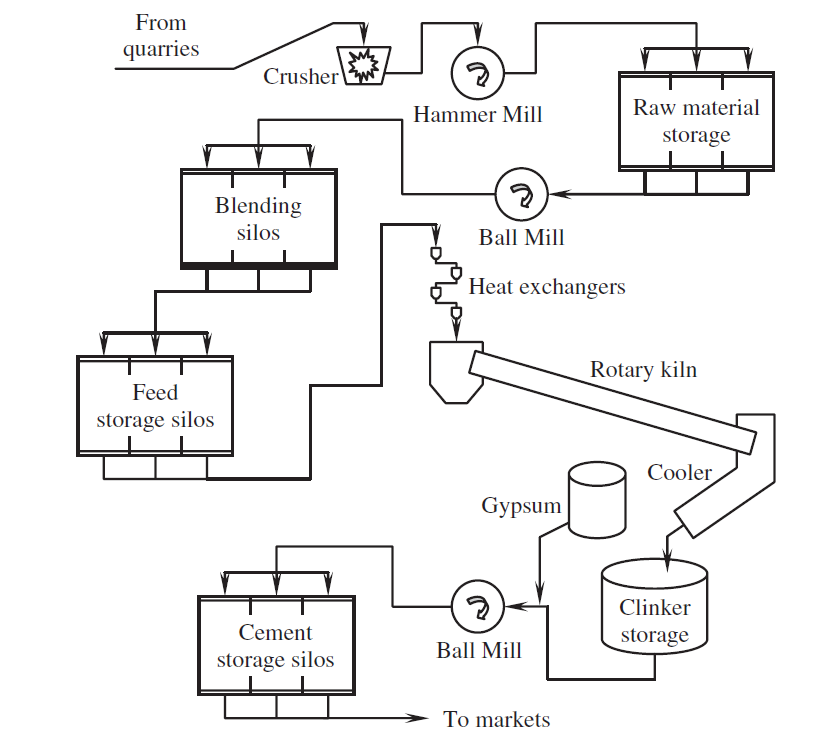
Portland cement is made by the mixing of limestone and clay or shale, then heating the mixture in a rotary kiln at a temperature of 1450 C. the materials supplied from quarries are crushed and blended into a uniform composition and fine size enough to enable the reaction at the rotary kiln. The heating of raw material will produce clinker. The clinker is grounded with gypsum to form the portland cement. Figure 1 showing the stages of manufacturing portland cement. The basic raw materials used to produce cement is limestone, clay, and iron ore. Figure 1 construction management: concrete construction bridge construction:How to become a bridge engineer The chemical composition of cement: Major compounds: major compounds of portland cement is listed in table number 1. C2S and C3S occupy 68% to 75% of portland cement. Since the primary constituents of Portland cement are calcium silicates, we can define Portland cement as a material that

Hydraulic and Non-hydraulic Cement

Image
There are two main types of cement. Hydraulic and non-hydraulic cement. Nowadays, hydraulic cement is used widely in the construction of concrete structures. On the other hand, the using of non-hydraulic cement decline sharply because it's less efficient and feasible compared to hydraulic cement. Figure 1 construction management: concrete construction bridge construction:How to become a bridge engineer non-hydraulic cement made from lime. Lime is formed from by the calcination of calcium carbonate(CaCo3) at a temperature higher than 825 C. CaCO3 → CaO + CO2 then calcium carbonate mixed with water to produce calcium hydroxide( Ca(OH)2 ) Cao + H2O → Ca(OH)2 non-hydraulic cement gain strength by the carbonation process. Excess water should evaporate entirely before the beginning of the carbonation process.  Ca(OH)2 + CO2 → CaCO3 + H2O non-hydraulic cement can't harden and gain strength underwater. The carbonation required

Types of Joints in Concrete Construction

Image
Joints are used in concrete structure for various reasons such as relieving the stresses resulting from the increase of concrete structure length due to temperature. There are four types of joints in concrete structures. Construction joint: for large structures such as a long slab it is challenging to place concrete at one time. Therefore the concrete pouring is divided into stages. The boundary between these concrete pours is known as construction joints. The location of construction joints should be predetermined before begin with the casting process. Construction joint shall be roughened and cleaned to ensure a proper bond with next pour. Shear keys should also be added to improve shear resistance. Figure 1 construction management: concrete construction bridge construction:How to become a bridge engineer Expansion joints: the purpose of forming an expansion joint in concrete is to accommodate the volume change of concrete structures. Expans

Corrosion inhibitor

Image
Corrosion of reinforcement steel in concrete structure is one of the significant threats that can weaken and reduce the durability of concrete structures. Concrete structures located in an aggressive environment such as coastal environment are more vulnerable to corrosion. Corrosion will adversely affect the reinforcement steel. Corrosion will occupy a bigger space which exerts stresses on concrete. These stresses will cause cracks and spalling of concrete, as shown in figure 1. Also, The steel cross-section will be reduced due to corrosion. The reduction of steel cross-section will result in the reduction of steel tensile strength.    Figure 1 construction management: concrete construction bridge construction:How to become a bridge engineer  The corrosion of reinforcement can be reduced and delayed by providing enough concrete cover, using epoxy-coated reinforcement, reducing the permeability of concrete by adding pozzolans such as micro silica, reduci

Corrosion mechanisms in reinforced concrete

Image
Corrosion of reinforcement steel in concrete structure is one of the significant threats that can weaken and reduce the durability of a concrete structure. Concrete structures located in an aggressive environment such as coastal environment are more vulnerable to corrosion. Corrosion will adversely affect the reinforcement steel. Corrosion will occupy a bigger space which will exert stresses on concrete. These stresses will cause cracks and spalling of concrete, as shown in figure 1. Also, The steel cross-section will be reduced due to corrosion. The reduction of steel cross-section will result in the reduction of steel tensile strength.    Figure 1 construction management: concrete construction bridge construction:How to become a bridge engineer  The corrosion of reinforcement can be reduced and delayed by providing enough concrete cover, using epoxy-coated reinforcement, reducing the permeability of concrete by adding pozzolans such as micro silica,

Compression Steel

Image
Reinforcement steel possesses excellent tensile strength, unlike concrete. Therefore it is common sense to place reinforcement in an area subjected to tensile stress. Occasionally steel is placed in the compression side of beams. Beams with reinforcement in tensile and compression side known as a doubly reinforced beam.   Figure 1 construction management: concrete construction bridge construction:How to become a bridge engineer In some cases, the size of the beam is reduced due to aesthetic or space requirement. Therefore we use compression reinforcement to increase the resisting moment of the beam. Adding reinforcement in the compression side will result in a beam with higher moment capacity compared to beam with a limited maximum reinforcement in the tensile side. By introducing steel in the compression side. Another resisting couple introduced to the beam. Also, compression reinforcement will increase the amount of curvature that a beam can stand

Jacking methods

Image
The jacking method will be determined based on several factors such as the number of strands, the shape of the post-tensioning duct and the profile shape of tendons. there are two methods used to tension prestressing steel. construction management: concrete construction bridge construction:How to become a bridge engineer Single (Mono) Strand Stressing  mono strands stressing is performed by stressing each strand individually. this method will be suitable for a limited number of strands. usually it is used in stressing building slabs. the strands will be placed side by side inside a flat-oval duct. therefore stressing strands one by one will not cause trapping of subsequent strands. This method can be used for multi-strand longitudinal strands only if there is no curvature in the tendon profile. the designer should consider the loss of the prestressing force due to elastic shortening. the loss of prestressing force should be considered for all subsequent stra

Concrete Durability Test ( Rapid Chloride Permeability Test)

Image
The permeability of concrete is playing a significant role in determining the service life of concrete, especially in an aggressive environment. The ingress of chloride will adversely affect the concrete. Chloride will cause reinforcement corrosion. The volume of corrosion is estimated to be 3 times the original volume of reinforcing bars. The increase of volume will exert stress on concrete that will lead to cracking and spalling of concrete. Also, corrosion will reduce the cross-section of steel and the tensile strength of reinforcement bars. The strength and durability of reinforced structure will be adversely affected.  construction management: concrete construction bridge construction:How to become a bridge engineer The rapid chloride permeability is a non-destructive test used to measure the resistance of concrete to chloride ion penetration. The migration of chloride through concrete is a slow process even if the permeability of concrete is high. The researche

Concrete durability tests( The depth of penetration of water under pressure in hardened concrete)

Image
The concrete structure service life depends on several factors such as workmanship, the quality of materials used in construction, the suitability of these materials to the surrounding environment. Concrete is the main component of concrete structures. Therefore if the quality of used concrete is good, the structure will live for a long time. The durability of concrete can be tested using different tests. One of them is The depth of penetration of water under pressure in hardened concrete. The principle of the test is applying water under pressure to concrete specimen then measure the depth of water penetration. Figure 1 showing the apparatus for the test.  Figure 1 construction management: concrete construction bridge construction:How to become a bridge engineer Procedure: The specimen after demolding shall be roughened at the area of applying water.   The test can be conducted at 7 or 28 days of concrete casting. Place the specimen at the apparat

Determination of the Cause's of Concrete Damage

Image
Concrete structures viewed as a durable structure. Proper design of concrete structures along with the appropriate placing of concrete will result in durable structures. Periodic maintenance will increase the concrete structure service life. construction management: concrete construction bridge construction:How to become a bridge engineer Old structures were built using old technology. At the time of construction, the methods of construction were old. The expected service life of these structures will be less than modern structures. Therefore periodic inspection and maintenance should be conducted to ensure and increase the service life of these structures. New concrete technology enabled the using of concrete in an extremely aggressive environment. The life of structure can be increased by developing and following a maintenance program. The maintenance of a structure is economical than taking no action. Structure in figure no:1 required expensive repairing or replac

Moment Diagrams Constructed by the Method of Superposition

Image
Shear and moment diagrams are very important to conduct a structural analysis for a member or structure. Also, the designer should know the shear and moment values applied to a member to determine the amount of reinforcement and member dimension. A structural engineer should have the ability to draw shear and moment diagrams . Superposition is one of the methods used to draw the moment diagram. In this method, the loads applied on beam taken individually. The moment diagram for each load drawn separately. The moment diagram for a beam is the sum of these diagrams for each load case. Figure 1 shows most of the load cases for a beam. Figure 1 To understand the principle of superposition let consider the simply supported beam in figure 2. the simply supported beam in figure 2 subjected to a distributed load of 4k/ft over half of the beam and moment of 300 k.ft at the middle of the beam. First, we will calculate the reaction at support A and B. for simplific

Shear and moment diagram part 4

Image
construction management: concrete construction bridge construction:How to become a bridge engineer construction management: concrete construction bridge construction:How to become a bridge engineer

Prestressing losses-Friction losses

Image
Applied prestressing force or jacking force will be reduced due to several reasons, the effective prestressing force will be jacking force minus prestress losses, prestress losses are categorized into, instantaneous losses such as friction, elastic shortening, anchorage setting. Time-dependent losses such as shrinkage of concrete, creep and stands relaxation. construction management: concrete construction bridge construction:How to become a bridge engineer Friction loss will occur over the whole length of the tendons, and it is related to two sources. The friction between tendon and duct due to change of duct profile. This loss is associated with the angular change of duct profile.  μ is the friction coefficient, and it is used to evaluate friction losses, the value of  μ related to duct material.  μ is not sufficient to predict friction losses, using  μ individually will not produce accurate results at the field. Wobble coefficient (K)  will be used in conjunctio

Popular posts from this blog

Bar Bending schedule (BBS)

Binding wire for steel reinforcement

Pile cap

Repairing of concrete bulging

stress-strain diagram for aluminium alloy and rubber

Non-working piles

Bridge Diaphragm

Nominal maximum size of coarse aggregate

shear key

The reasons behind the trimming of pile head

My photo
Mohammad
My name is Mohammad Hamdan, and I am a Civil/bridge Engineer with extensive professional background and experience in the field of construction. I have 10+ years of experience in the construction field. During my professional career, my emphasis has been placed on structural projects, mainly bridges, infrastructure and roads. Reading and practicing the design of structures is my passion.i was lucky to be a part of a big team that executed major highway interchanges. I believe in spreading the knowledge, thus, i compose these courses to share my experience and knowledge. My course focuses on the practical side of construction field. On other word, i am sharing some of what new engineers need to know about construction field. Beside working on construction field, i love writing some articles on my website ( curious civil engineer) Moreover, i wrote some engineering papers, you can check them  by searching my name on Google (Mohammad mamon Hamdan)