previously we discussed
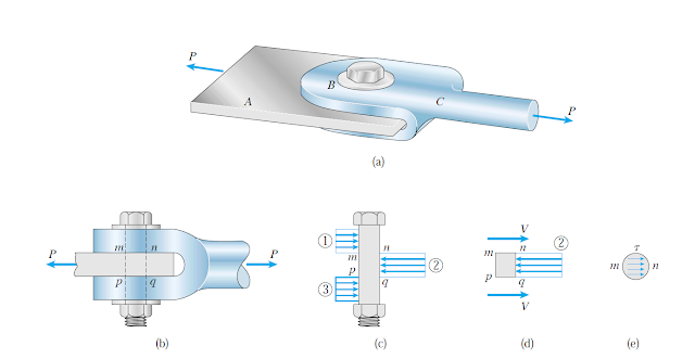
normal stress. here we will discuss shear stress. normal stress acting normal or perpendicular to the surface of the material. The shear stress acting tangential to the material surface. shear force always trying to shear the material. Figure below shows a clevis and bar connected by a bolt. a load equal P applied to the clevis. this load resisted by the bar. the connecting bolt subjected to bearing stress and shear stress. bearing stress also known as contact stress is generated in the area of contacts. for our example bearing stress is generated between the contact area of clevis and bolt. also between bar and bolt. as showing figure 1-C. figure 1-C showing the distribution of stresses. the stress assumed to be uniform for simplicity. bearing stress calculated by dividing the total bearing force by the projection of the contact area
σ=Fb/Ab
As illustrated in figure 2 the projection area for bearing stress for clevis Ab=F*d , for the bar Ab=G*D
 |
| Figure 1 |
 |
Figure 2
in figure 1-D we can notice that the applied force is tending to shear or cut the bolt. and the bolt shear stress resisting this tendency. for this example, there are two shear plans. the two planes are mn and pq. for this case the shear force for each plane equal P/2. the shear stress equals the shear force divided by shear planes. figure 3 showing bolt deformation under the effects of double shear force.
 |
| Figure 3 |
Figure 4 showing double bolting. in this case, the shear force V will be equal to P/4 because the force from each bar will be distributed between these two bolts. we have two planes of shearing similar to the previous example.
|
 |
Figure 4
The average shear stress on shear plane
Τav=V/A
where A is the cross-section area at the location of the shear force.in our example A= the cross section area of the bolt.
calculating shear stresses is very important. equipment, steel structure, and reinforced concrete shall be checked for shear failure. in concrete structure the shear diagram is drawn for each member and shear reinforcement area (stirrups) and member dimension determined considering the maximum shear obtained from shear diagram. figure no 5 showing shear diagram for a simply supported beam.
 |
Figure 5
|
|


Comments
Post a Comment