


Example 1: Design of T shape beam
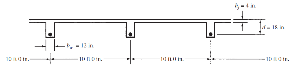
Design a T beam for the floor system shown in Figure 1, for which bw and d are given.MD = 80 ft-k, ML = 100 ft-k, fc' = 4000 psi, fy = 60,000 psi, and simple span = 20 ft.
Effective Flange Width
Mu=1.2MD+1.6ML=256ft-K
assuming ϕ=0.9
Mn=Mu/ϕ=284.4ft-K=3,412,800in-lb
Checking Minimum Reinforcing
As, min=3*√fc'*bw*d/fy and not less than 200*bw*d/fy
As, min=3*√fc'*bw*d/fy=0.68in2 and not less than 200*bw*d/fy=.72in2<3.25in2 ok
checking if ϕ=0.9
c=a/β=0.96/0.85=1.13 in
εt=((d-c)/c)*0.003=0.045>0.005 assumption is ok
Figure 1
Effective Flange Width
- 1/4ft × 20 ft = 5 ft = 60 in.
- 12 in. + (2) (8) (4 in.) = 76 in.
- 10 ft = 120 in.
bf=60 in, ACI Code (8.12.2) calls for a smaller width with an assumed uniform stress distribution for design purposes.
Mu=1.2MD+1.6ML=256ft-K
assuming ϕ=0.9
Mn=Mu/ϕ=284.4ft-K=3,412,800in-lb
Assuming a Lever Arm z Equal to the Larger of 0.9d or d − (hf/2)
z=0.9*d=0.9*18=16.2in
Steel trial area
As*fy*Z=Mn
As=3,412,800/(60,000*16.2)
As=3.51in2
computing Z and a
0.85*fc'*bf*a=As*fy
a=(As*fy)/(0.85*fc'*bf)
a=1.0326in then neutral axis in the flange
z=d-a/2
z=18-1.03/2=17.48in
computing As using revised Z value
As=Mn/(fy*Z)
As=3,412,800/(60000*17.48)=3.25in2
compute revised a and Z
a=(As*fy)/(0.85*fc'*bf)
a=(3.25*60,000)/(0.85*4000*60)
a=0.96in
Z=18-0.95/2=17.52in
computing As using revised Z value
As=Mn/(fy*Z)
As=3,412,800/(60000*17.52)=3.24 in2 ok
As, min=3*√fc'*bw*d/fy and not less than 200*bw*d/fy
As, min=3*√fc'*bw*d/fy=0.68in2 and not less than 200*bw*d/fy=.72in2<3.25in2 ok
checking if ϕ=0.9
c=a/β=0.96/0.85=1.13 in
εt=((d-c)/c)*0.003=0.045>0.005 assumption is ok


Comments
Post a Comment