Posts

Showing posts with the label Design

Subscribe to My You tube channel

Recycled aggregates

Image
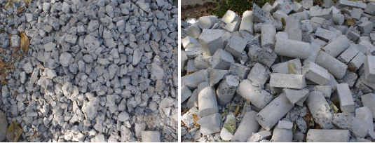
The steep growth of the construction sector resulted in massive consumption of earth resources. The using of recycled aggregates will help in preserving the environment. The construction waste amount increased rapidly in recent years. Undoubtedly, the recycling of construction waste such as concrete will help in safeguarding environments resources and ensure sustainability. Recycled aggregates can replace part of natural aggregates used in concrete. Natural aggregates can be replaced by 20% of recycled aggregates for all concrete classes, and 100% for a limited classes of concrete according to RILEM Technical recommendations. The using of recycled aggregates will produce concrete with lesser compressive strength and quality. Figure 1 construction management: concrete construction bridge construction:How to become a bridge engineer Most of the recycled aggregates produced from concrete waste. Aged concrete such as old foundation, bridges, building, and conc

Fiber reinforced shotcrete

Image
The conventional unreinforced concrete is a brittle material. Similarly, the unreinforced shotcrete is a brittle material that cracks when subjected to tensile stresses. The addition of fibers to shotcrete will improve the properties of shotcrete. The ductility and impact resistance will be enhanced. The reinforced shotcrete material will not only be capable of enduring post cracks loading but also often displays an increase in ultimate strength, in particular, the tensile strength. The used fibers can be steel fibers, glass fibers, and synthetic fibers.  Figure 1 construction management: concrete construction bridge construction:How to become a bridge engineer The glass fibers are made from a special zirconium alkali-resistant (AR) glass to resist the deterioration in high alkaline Portland cement. Glass reinforced shotcrete required a special gun and delivery system. The process of applying glass-reinforced shotcrete is different from applying conventi

Carbonation of concrete

Image
Concrete structures are renowned for their durability. Reinforced concrete is used widely over the globe to build bridges, tunnels, roads, and many other types of structures. The durability of concrete can be reduced by the ingress of aggressive chemicals such as chloride, freeze and thaw cycles, and the carbonation of concrete.  construction management: concrete construction bridge construction:How to become a bridge engineer Concrete is alkaline. The Ph of concrete at pouring approaches 13. Concrete alkalinity provides protection for the steel against corrosion. Concrete forms a thin passive layer that minimizes the rate of steel corrosion. The concrete passive layer reduces the corrosion of steel to 1 µm per year. Steel without concrete passive layer protection will undergo corrosion of 1000 times higher. Corrosion of reinforcement steel can severely affect the structure. Corrosion of steel can result in cracks and spalling of concrete. Figur

Plastic settlement cracks

Image
Plastic settlement occurs as a result of restraining the settlement of concrete. Plastic settlement cracks are so-called because it is formed while the concrete is still plastic. Plastic settlement cracks are different from shrinkage cracks by its distinguished pattern. Plastic settlement cracks tend to mirror the restraining elements, such as reinforcing steel. Plastic settlement cracks may become noticeable at an early stage. However, the cracks often noticed after a few hours of concrete placing. The cracks occur while the concrete is plastic, and the bleeding water is rising. These cracks can seriously affect reinforced concrete that exposed to harsh environments. These cracks will facilitate the ingress of aggressive chemicals such as chloride and sulfate. The ingress of chloride will result in corrosion of steel reinforcement, which may reduce the service life of the structure. Figure 1 construction management: concrete construction bridge construction:Ho

Structure failure (faulty construction-case study)

Image
Faulty construction can result in severe consequences that can lead to structural failure. Undoubtedly, faulty construction is the most important cause of structural failure. Poor communication, poor workmanship, lack of supervision team experience, lack of work ethics, and discipline are the most causes of faulty construction. Many practices in the construction field are wrong, and it is carried out daily as correct practices. Labor using salt sand for concrete, reducing the amount of reinforcement, early removal of falsework, bad riveting, improper tightening torque on nuts, and modifying the design on the field without informing designers are examples of faulty practices. Faulty practices must be checked firmly and stopped to avoid undesirable consequences.  construction management: concrete construction bridge construction:How to become a bridge engineer In 1981 a walkway collapsed in Hyatt Regency Hotel, Kansas City, while a massive number of people gather

Compression Steel

Image
Reinforcement steel possesses excellent tensile strength, unlike concrete. Therefore it is common sense to place reinforcement in an area subjected to tensile stress. Occasionally steel is placed in the compression side of beams. Beams with reinforcement in tensile and compression side known as a doubly reinforced beam.   Figure 1 construction management: concrete construction bridge construction:How to become a bridge engineer In some cases, the size of the beam is reduced due to aesthetic or space requirement. Therefore we use compression reinforcement to increase the resisting moment of the beam. Adding reinforcement in the compression side will result in a beam with higher moment capacity compared to beam with a limited maximum reinforcement in the tensile side. By introducing steel in the compression side. Another resisting couple introduced to the beam. Also, compression reinforcement will increase the amount of curvature that a beam can stand

Structural analysis for cable subjected to point load

Image
Cables are used to support many structures. We can find cables supporting electrical transmission towers, cable-stayed bridge, and suspension bridges. Cables are used almost every day in the construction sites. Cranes using cables to assist in loading and shifting materials. Cables are assumed to be flexible and inextensible. The flexibility of cables means the cable will not be subjected to shear or bending moment. The force acting to cables is always tangent at points along its length. Inextensible means the cable will preserve the same geometry after applying the loads. This means the cable segment will keep the same shape after applying the load, and it is treated as a rigid body.  construction management: concrete construction bridge construction:How to become a bridge engineer The analysis of cables is similar to other structures. Cables will carry only axial forces without any shear and bending. Considering the example in figure 1. the number of unknown force

Example 1: Design of T shape beam

Image
Design a T beam for the floor system shown in Figure 1, for which bw and d are given.MD = 80 ft-k, ML = 100 ft-k, fc' = 4000 psi, fy = 60,000 psi, and simple span = 20 ft. Figure 1 construction management: concrete construction bridge construction:How to become a bridge engineer Effective Flange Width 1/4 ft × 20 ft = 5 ft = 60 in. 12 in. + (2) (8) (4 in.) = 76 in. 10 ft = 120 in. bf=60 in , ACI Code (8.12.2) calls for a smaller width with an assumed uniform stress distribution  for design purposes. Mu=1.2MD+1.6ML=256ft-K assuming Ï•=0.9 Mn=Mu/Ï•=284.4ft-K=3,412,800in-lb Assuming a Lever Arm z Equal to the Larger of 0.9d or d − (hf/2) z=0.9*d=0.9*18=16.2in Steel trial area As*fy*Z=Mn As= 3,412,800 /(60,000*16.2) As=3.51in2 computing Z and a 0.85*fc'*bf*a=As*fy a=(As*fy)/(0.85*fc'*bf) a=1.0326in     then neutral axis in the flange z=d-a/2 z=18-1.03/2=17.48in computing As using revised Z value

Shear and Moment Diagrams for a Frame

Image
Frames are made from connecting several members together. The procedure for drawing shear and moment diagrams for a frame is similar to  drawing shear and moment diagram for a beam . The reaction at support should be determined. Then the internal forces should be determined at the end of members using the method of section. Provided all loadings are resolved into components acting parallel and perpendicular to the member’s axis, the shear and moment diagrams for each member can then be drawn as described previously. You can select sign convention for moment diagram. We can draw a positive moment diagram on the tension side of the frame. Here we will draw the positive moment diagram on the compression side of the frame. Examples Figure 1 Figure 2(reactions) Figure 3(shear and moment diagram) Figure 4 Figure 5(shear and moment diagram) construction management: concrete construction bridge construction:How to become a bridge engineer

Shear and moment diagrams part 2

Image
construction management: concrete construction bridge construction:How to become a bridge engineer

Shear and moment diagram part 1

Image
construction management: concrete construction bridge construction:How to become a bridge engineer construction management: concrete construction bridge construction:How to become a bridge engineer

Design of bridge pier

Image
Design brief The structural member is subdivided into two regions. Region B (BERNOULLI), where the beam theory assumptions are applicable. The main assumptions of beam theory are the cross-section of beam do not deform significantly under applied load, and beam cross-section remains planner and normal to deform axis of the beam. On the other hand, Portions of a structure where the beam theory is not applicable classified as region D. discontinuity, change in section dimension, opening, nodes and connection of girders and beams are examples of D-region. Members with vary cross-section such as pier cap can be designed using strut and tie method. Strut and tie method is suitable for designing members where beam theory is not applicable. Moreover, it is a conservative method and can be used for the B region. The main concept of the STM method is to represent the flow of internal forces using a truss system consist of strut, ties, and nodes. The modeling of strut and tie is a bit chal

Popular posts from this blog

Bar Bending schedule (BBS)

Binding wire for steel reinforcement

Pile cap

Repairing of concrete bulging

stress-strain diagram for aluminium alloy and rubber

Bridge Diaphragm

Non-working piles

Nominal maximum size of coarse aggregate

shear key

The reasons behind the trimming of pile head

My photo
Mohammad
My name is Mohammad Hamdan, and I am a Civil/bridge Engineer with extensive professional background and experience in the field of construction. I have 10+ years of experience in the construction field. During my professional career, my emphasis has been placed on structural projects, mainly bridges, infrastructure and roads. Reading and practicing the design of structures is my passion.i was lucky to be a part of a big team that executed major highway interchanges. I believe in spreading the knowledge, thus, i compose these courses to share my experience and knowledge. My course focuses on the practical side of construction field. On other word, i am sharing some of what new engineers need to know about construction field. Beside working on construction field, i love writing some articles on my website ( curious civil engineer) Moreover, i wrote some engineering papers, you can check them  by searching my name on Google (Mohammad mamon Hamdan)