Posts

Showing posts with the label mechanics of material

Subscribe to My You tube channel

Allowable stress and allowable load
Image
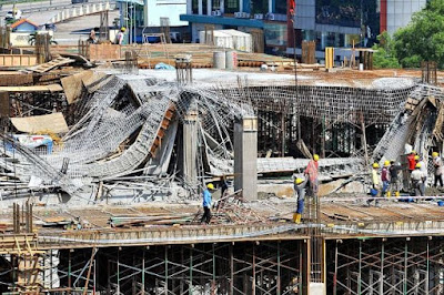
Designing a structure required a good knowledge of materials strength and load capacity. the required load to be supported or transfer by structure shall be less than the structure capacity. if the structure subjected to a load larger than it is capacity it will fail. therefore the actual strength of structure shall exceed the required strength. the ratio of the actual strength of the structure to required strength is known as the factor of safety. Ƞ=ِAcutual strength/required strength the factor of safety shall be higher than one. the factor of safety magnitude can range from slightly above 1 to 10 or more. Determining the magnitude of the factor of safety is difficult because strength and failure have a different meaning. actual strength of the material is the load and stress capacity of a structure. failure of a structure may mean the total collapse of the structure. or it could mean the excessive deformation of the structure. required load for the second case will be les

Hook's law in shear

Image
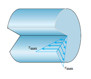
Direct shear test can be used to determine materials behavior in shear. also, the torsion test can be used to determine shear properties. materials such as hollow, circular tubes will be subjected to torsion by twisting. torsion will produce shear over the cross-section and longitudinal planes of materials as shown in figure no:1. construction management: concrete construction course   bridge construction:How to become a bridge engineer course Figure 1 using these tests. the stress-strain diagram can be established. the stress-strain diagram for the shear test will be similar in shape to the stress-strain diagram for the tension test. despite the similarity in shapes. the magnitude will be different.stress-strain diagram in shear can be used to determine proportional limits, yield stress, modulus of elasticity and ultimate stress in shear. for example, the yielding stress in shear for structural steel is 0.5 to 0.6 time the yield stress in tension. for materials w

Poisson's ratio

Image
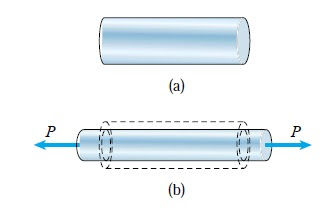
if we stretch a rubber band. the length of the rubber will increase. on the other hand, the diameter will decrease. increase in length represents the axial strain. the decrease in diameter represents the lateral contraction. if we applied a uniaxial tension load for materials such as prismatic steel bar. tension load will cause axial strain and lateral strain normal to the direction of axial load. the lateral and axial strain will be proportional if the applied stress within the elastic region. for steel stress within the elastic region, the amount of lateral strain will be small and not visible. figure no:1 illustrating the concept. figure 1-a shows a prismatic bar prior to loading. figure 1-b shows the bar after loading. we can notice the increase of bar length(axial strain) and the decrease of bar diameter(lateral contraction) Figure 1 construction management: concrete construction course   bridge construction:How to become a bridge engineer course ν=-( ε'

Hooke's law

Image
Hooke's law named for the famous English scientist hook. hook investigate the relationship between stress and strain. He investigated and observed the amount of stretching of wires for different materials under loads. He notices a proportional elongation under proportional loads. then Hook developed the equation between axial stress and strain σ=E* ε where  σ= is the axial stress  E= is the modulus of elasticity ε= is the axial strain  The above equation expresses the linear relationship between stress and strain for a bar in simple tension or compression. this relationship is valid at the linearly elastic region for materials. it is known that the materials at the elastic region can recover the strain and the stress-strain curve at the elastic region exhibits a linear relationship for most of the materials. structural steel is an example of materials that exhibits a linear stress-strain relationship at the elastic region. usually, structures and machines designed

Creep and relaxation

Image
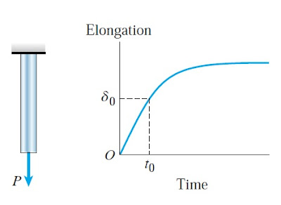
creep is a time-dependent deformation due to  constant load. we discuss before the elastic and plastic behavior of the materials under loading and unloading. here we will discuss the effect of loading materials for a period of time. in figure no:1 the bar is loaded with a force P. at time of loading (t o ) the elongation equal  δ 0 .  if the applied load on bar maintained for a long  time. the strain of the  material will increase gradually without any increase in applied load   as shown in figure 1. the gradual increase in strain for a permanent or constant load  known as creep.  In prestressing concrete creep cause losing of prestressing force. therefore it is calculated and added to the  jacking force to compensate for losses. also ,  creep can create undulation of bridge deck. this can be adjusted by adjusting deck level upward in an amount  equal to expected creep so when creep occurred the level of deck will be in required position. Figure-1 Relaxation of materials is

Elastic and plastic behavior of materials

Image
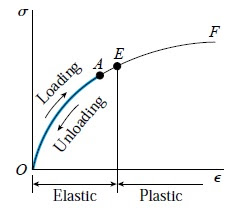
stress-strain curve for materials represents the behavior of materials under loading. The materials act elasticity if loaded within the elastic region. in figure no:1 the material loaded in tension from point O to point A. this load occurred within the elastic region. if we remove the load. all the strain will be recovered and specimen or material will go back to original shape and size. it is not necessary for the stress-strain curve to be linear at elastic region. so materials will recover the strain totally if it is loaded and unloaded within elastic region. construction management: concrete construction bridge construction:How to become a bridge engineer Figure-1 if the material loaded beyond the elastic region. in this case, part of the strain will be recovered after unloading. in figure no:2 we loaded the material to point B beyond the elastic region. if we unload the material. the material will follow line B-C. line B-C is parallel to the initial portion o

stress-strain diagram for aluminium alloy and rubber

Image
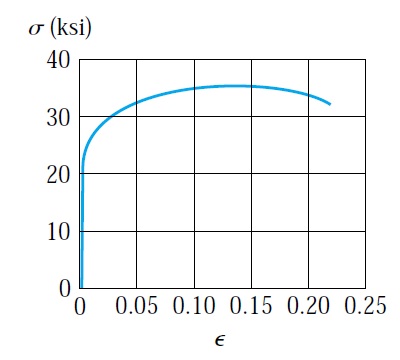
figure no:1 showing the stress-strain diagram for aluminum alloy. we can notice from the stress-stress diagram that aluminum has a considerable ductility. despite the absence of explicit yield point as in structural steel . the initial portion of the stress-strain curve is linear with a recognizable proportional limit. the proportional limit for aluminum alloy ranges from 70 to 410 Mpa (10 to 60 Ksi). aluminum alloy undergoes large strain before failure. ultimate stress ranges from 140 to 550 Mpa (20 to 80 Ksi). construction management: concrete construction bridge construction:How to become a bridge engineer Figure-1 Yield stress for aluminum alloy can be determined by drawing offset line parrel to the linear portion of the stress-strain curve. the straight line offset by a standard strain such as 0.002. the intersection point with the stress-strain curve is the point of yield stress. figure no:2 illustrates the concept of offset method. yield stress acquire

Shear stress

Image
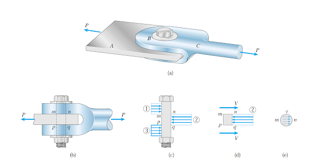
previously we discussed normal stress . here we will discuss shear stress. normal stress acting normal or perpendicular to the surface of the material. The shear stress acting tangential to the material surface.  shear force always trying to shear the material. Figure below shows a clevis and bar connected by a bolt. a load equal P applied to the clevis. this load resisted by the bar. the connecting bolt subjected to bearing stress and shear stress. bearing stress also known as contact stress is generated in the area of contacts. for our example bearing stress is generated between the contact area of clevis and bolt. also between bar and bolt. as showing figure 1-C. figure 1-C showing the distribution of stresses. the stress assumed to be uniform for simplicity. bearing stress calculated by dividing the total bearing force by the projection of the contact area  σ=Fb/Ab As illustrated in figure 2 the projection area for bearing stress for clevis Ab=F*d , for the bar Ab=G*D co

Modulus of elasticity

Image
Modulus of elasticity measures material resistance to deforming  elastically   under applied stress. It is important material properties describing it is stiffness. modulus of elasticity can be determined from the stress-strain diagram by measuring the slope of the elastic region. stiffer material means more stress required to deform the material and this means higher modulus of elasticity construction management: concrete construction bridge construction:How to become a bridge engineer E=σ/ε where  σ the stress causing the deformation. stress is the applied force divided by the area.  ε is the strain and it is defined as the change in length divided by original length = ∆L/L0= (L1-L0)/L0 Graphical Determination of Modulus of Elasticity Modulus of elasticity can be determined from the stress-strain diagram. modulus of elasticity is the slope of linear(elastic) region. the stress-strain diagram for a material can be drawn by testing material for

Mechanical properties of structural steel

Image
Structural steel(mild steel or low-carbon steel) used in construction widely. in concrete structure steel used to reinforce concrete and enhance its properties. the steel structure is another example of steel importance in the construction industry. therefore it is important to determine steel properties and how steel behaves under load. determination of mechanical properties of steel done by testing a small specimen under increasing load and the corresponding deformation such as the change in length and diameter is determined. construction management: concrete construction bridge construction:How to become a bridge engineer Structural steel will be tested for tension. the loads and corresponding deformation will be measured and recorded to generate a stress-strain diagram. stress-strain diagram was originated by jacob Bernoulli (1654–1705) and J. V. Poncelet (1788–1867). stress-strain diagram provides important information about material properties and behavior. 

Normal stress and strain

Image
Stress express the strength of material per unit of area. if an axial force in tension (P) subjected to a prismatic bar of cross-sectional area (A). prismatic means a member of the same cross-section through the length. in this case, the stress can be calculated using the following equation σ=F/A construction management: concrete construction bridge construction:How to become a bridge engineer the figure below shows a prismatic bar subjected to a tension force P. in figure B depicts the bar before being subjected to force. we can notice the original length of bar equal L. after subjecting the bar to force P the bar length increased. this increased in length induced by stress imposed in the bar. the change in bar dimension known as strain. tension force will cause an increase in bar length in the contrary the compression force will reduce the length of the bar. when the force applied at perpendicular to cut surface as shown in figure d this will be known as normal

Popular posts from this blog

Bar Bending schedule (BBS)

Binding wire for steel reinforcement

Pile cap

Repairing of concrete bulging

stress-strain diagram for aluminium alloy and rubber

Non-working piles

Bridge Diaphragm

Nominal maximum size of coarse aggregate

shear key

The reasons behind the trimming of pile head

My photo
Mohammad
My name is Mohammad Hamdan, and I am a Civil/bridge Engineer with extensive professional background and experience in the field of construction. I have 10+ years of experience in the construction field. During my professional career, my emphasis has been placed on structural projects, mainly bridges, infrastructure and roads. Reading and practicing the design of structures is my passion.i was lucky to be a part of a big team that executed major highway interchanges. I believe in spreading the knowledge, thus, i compose these courses to share my experience and knowledge. My course focuses on the practical side of construction field. On other word, i am sharing some of what new engineers need to know about construction field. Beside working on construction field, i love writing some articles on my website ( curious civil engineer) Moreover, i wrote some engineering papers, you can check them  by searching my name on Google (Mohammad mamon Hamdan)