Posts

Showing posts with the label Foundation

Subscribe to My You tube channel

Waterstop for concrete structures

Image
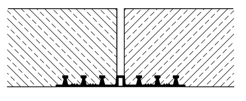
Large structures are usually poured in different stages. It is not possible to cast large structures at one time. The casting of large structures at one time will require a long time, a huge number of workers and equipment. In some cases, the geometric and sequence of work will require the casting of a structure in several stages. Pouring of concrete will result in forming construction joints between different concrete pours. Water-stop is usually used for various structures such as dams, water treatment facilities, storage tanks, culvert, slab on grade, and parking garage. The use of water-stop for storage tanks is critical. Water-stop will prevent the liquid from leaking. So, in general, water-stop will be used for structures that in direct contact with water. Water-stop will prevent the seepage of water from the construction joint. We have two types of water-stop. External water-stop fixed on the wet side of a concrete structure, as shown in figure no:2. External water-stop will pr

Tremie pipe for piles

Image
Tremie pipe can be defined as segments of steel pipe. These segments will be connected together and used to cast a drilled pile foundation. Using of tremie pipe will prevent the segregation of concrete. Tremie pipe will ensure that the concrete is not thrown from a huge height. As we know, placing the concrete from any distance higher than 1.5 m can cause concrete segregation. Therefore, tremie pipes are used. The tremie pipe segment will be connected to a length equal to pile length. Then it will be lowered to the bottom of the pile hole. Figure no:1 shows a tremie pipe inserted inside the casing and steel cage of a pile before beginning with the concerting of the pile.  Figure 1 We should always ensure that the tremie pipe external diameter is suitable. We should ensure that the tremie pipe doesn't clash with the steel cage or any spacer blocks. Also, we should make sure that the internal diameter of the tremie pipe is sufficiently bigger than the maximum size of concrete aggrega

Tunnel lining systems-Ribbed system

Image
Ribbed supporting system has been used for many years to support tunnels. The ribbed supporting system is based on steel ribs supporting tunnels. The implementation of this system involves the installation of rolled steel sections around the circumference at specified spaces. The formation of gaps between the steel ribs and the ground is very common. These gaps should be suitably wedged to avoid excessive deformation of the ground. It is essential to ensure that the loads are distributed evenly by the steel support around the tunnel profile. Subjecting of steel support to point load will significantly reduce their ultimate capacity.  Figure 1 The steel ribs can be combined with shotcrete concrete. The shotcrete concrete will be applied before the erecting of ribs. The applying of a layer of shotcrete concrete will reduce the problems of gaps between ribs and surrounding ground, which minimize the wedging problems. Then another layer of shotcrete can be applied after th

Mechanical splicing of reinforcement steel

Image
As we know, the reinforcement steel length is limited. For long structural members, the reinforcement steel bars should be overlapped or spliced to produce the required length of reinforcement. Mechanical splicing of reinforcement is used widely in the construction industry. Threaded couplers are a widespread type of mechanical splicing. Threaded couplers are sub-categorized into taper and parallel threaded couplers. The cross-section and length of the coupler will depend on the grade of the reinforcement rebar. Taper threaded coupler is the simplest type of threaded coupler. This type of coupler can be used for columns and horizontal applications. But it is difficult to in rafts or other applications where it is difficult to turn and tighten the rebars. In general, the length of taper threaded couplers is more than parallel couplers. Taper threaded couplers are designed, taking into ac­count defects of the rebar such as undersizing, skewness, and oblongness of the rebar. 

Causes of Damage to Concrete-sulfate deterioration

Image
Sodium magnesium and calcium sulfates are salts that can react with hardened concrete and cause deterioration for concrete structures. Sodium magnesium and calcium sulfates react with hydrated lime and hydrated aluminate in cement. This reaction will produce calcium sulfate and calcium sulfoaluminate. The volume of these products is greater than the volume of the cement paste, which undergoes the reaction with sulfates salts. This reaction will cause a destructive volume change. The increase of existing concrete will generate stress, which may result in concrete cracking and spalling. The using of sulfate resistance cement is recommended where the sulfate concentration is high. Sulfate resistance cement or cement type V will resist the sulfate reaction. Type V cement has a low calcium aluminate content, which enables this cement type to provide a good resist the sulfate deterioration. Therefore it should be specified and used when it is recognized that concrete must be exposed to

Concrete repair-selecting the repair method

Image
Repairing concrete structure passes through various stages. Selecting the correct repair method will depend on completing the previous steps, such as determining the cause of concrete damage, evaluate the extent of the damage, and assess the need for repair. The completion of these steps will define the type of conditions the repair must resist, the available repair construction time period, and when repairs must be accomplished. The data collected from performing these steps will help in selecting which of the 15 standard methods is suitable and durable for repairing the damaged concrete structure. Figure 1 In general, the old concrete surface should be prepared before beginning with the repairing process. It is essential to remove all unsound concrete before applying the repairing. Improper preparing of damaged concrete structure will result in unsatisfactory repair with low durability. The first step in preparing the old concrete surface is the saw cutting of repairin

Fore-poling (ground improvement for tunnel excavation)

Image
This technique used to improve the ground and limiting the decompression of the crown of the excavation for tunnels. Steel bars (dowels) or steel plates(forepoles) are installed in the upper third or quarter of the excavation. Dowels and forepoles installed ahead of the tunnel excavation from the face periphery. Figure no:1 showing the installation of dowels and forepoles before commencing with further excavation of tunnels to stabilize the soil ahead. Figure 1 construction management: concrete construction bridge construction:How to become a bridge engineer Steel bars or dowels are similar to the one used for rock dowels. Dowels are installed from within the tunnels. Dowels are placed above a lattice girder. Dowels will be positioned at an angle to the direction of excavation, as shown in figure no:2 if the ground is very dense and hard. The dowels will be installed in a predrilled hole. The predrilled hole will be filled with grout before installing the do

Structure failure (collapse of sky line plaza)

Image
In 1973 one of skyline plaza collapsed. 14 workers died, and 34 were injured as a result of the tragic failure of the structure. The construction of the building was not completed at the time of the collapse, and the building was not due to open until six months. The primary reason behind the failure of the sky is the wrong practices in the field. There was no flaw in the design, and the structural collapse would be easily avoided if the contractors, engineers, and supervisors follow project specifications, guidelines, and correct construction practices. Figure 1 construction management: concrete construction bridge construction:How to become a bridge engineer The investigations showed that the shoring or falsework that supporting the 23rd floor was removed. At the time of removal, the concrete of columns and floors didn’t attain the designed strength. At the same time, more concrete placed for the 24th floor, which overload the columns. The columns c

Recycled aggregates

Image
The steep growth of the construction sector resulted in massive consumption of earth resources. The using of recycled aggregates will help in preserving the environment. The construction waste amount increased rapidly in recent years. Undoubtedly, the recycling of construction waste such as concrete will help in safeguarding environments resources and ensure sustainability. Recycled aggregates can replace part of natural aggregates used in concrete. Natural aggregates can be replaced by 20% of recycled aggregates for all concrete classes, and 100% for a limited classes of concrete according to RILEM Technical recommendations. The using of recycled aggregates will produce concrete with lesser compressive strength and quality. Figure 1 construction management: concrete construction bridge construction:How to become a bridge engineer Most of the recycled aggregates produced from concrete waste. Aged concrete such as old foundation, bridges, building, and conc

Silica-Fume/ Polymer modified shotcrete

Image
Silica fume is a fine nanocrystalline pozzolanic material that used to enhance concrete characteristics. Silica fume improves concrete compressive strength, bond strength, impact resistance, and it reduces concrete permeability. Using silica fume will increase the concrete structure's durability and strength. In shotcrete, silica fume used to improve the bonding strength of shotcrete with the existing surface. Additionally, silica fume will improve shotcrete cohesiveness. Thicker layers of shotcrete can be applied in a single pass owing this to increasing of cohesion. Moreover, silica fume will increase the resistance of fresh shotcrete to wash out where fresh shotcrete is subjected to water flow. Finally, silica fume will significantly reduce the rebound of shotcrete.  figure 1 construction management: concrete construction bridge construction:How to become a bridge engineer The adding of silica-fume will improve hardened and un-hardened shotcrete

Pile heave

Image
Driving piles will cause soil displacement. As a result, the previously driven pile will move upward and laterally. Pile heave value directly proportional to soil displacement. Therefore, as the number of driven piles increased pile heave will increase. The heave in cohesive soil is significant. As a result, the heave should be considered in the design stage. Using low displacement piles and improved method of installation (such as predrilling to reduce soil displacement) may consider if the calculated heave values are enormous. Figure 1 construction management: concrete construction bridge construction:How to become a bridge engineer In the events of adjacent piles heave while driving new piles more than 13 mm for end bearing piles. Pile shall be re-driven. Similarly, adjacent piles shall be re-driven if the upward movement is more than 38 mm for friction piles. Figure 2

Driven piles

Image
Driven piles have been used widely as a foundation for different structures. In this type of foundation. Piles are driven to soil mechanically using a hammer. There are enormous types of driven piles. construction management: concrete construction bridge construction:How to become a bridge engineer  Steel H Piles Section of H-pile consists of flange and web, as shown in figure no:1. They are driven using a high impact hammer, and the likelihood of pile damage is low. H-piles resists the loads through skin friction or end bearing or both. Since the displacement of soil is minimal, this type of piles can be driven into dense granular soil or stiff clay layers. Although some problem during driving may arise. Plugging is one of them. After driving the pile to a certain level. soils will adhere to pile web and between the flange creating a closed end. This will change the pile to displaced pile and complicate pile driving. H-piles should be protected a

Soil texture (fine grained, coarse grained)

Image
Soil classified into fine-grained and coarse-grained. Determination of soil texture depends on soil particle size, shape, and distribution. Gravel and sand are coarse textured. Clay and silt composed of predominantly tiny materials cant be seen by naked eyes. Therefore they are considered as fine-grained.  Figure 1 construction management: concrete construction bridge construction:How to become a bridge engineer Engineering behavior is related to soil texture, especially for coarse-grained soil. Classification of soil based on texture is more common in  Agronomy  (branch of agricultural science that deals with the study of crops and the soils in which they grow) more than in engineering. The soil texture classification terms(sand, gravel, silt, and clay) is still useful for the general sense in geotechnical engineering. For example, fine-grained soil behavior affected greatly by adding water. Adding water affects the particle interaction, and this will

Volumetric and mass relationship for soil

Image
Soil composed of solid particles with voids, voids will be filled with air or water or both. solid particles composed of different materials particles, the total volume of soil will be the algebraic summation of solid volume Vs and the volume of voids Vv. the volume of voids is the summation of the volume of air void Va and water void Vw. figure one depicting a soil sample with a different volume component of a soil mass. Figure 1 construction management: concrete construction bridge construction:How to become a bridge engineer The phase diagram in figure 2 representing the different component of soil volume on the left side and the masses of the soil at the right side. using these volumes we can find the volumetric ratio's Figure 2 there is three volumetric ratio's, void ratio, porosity and the degree of saturation. these ratios are important in geotechnical engineering Void ratio, e e=Vv/Vs       the value of void ratio e expre

Load transfer mechanism for piles

Image
piles are used for a structure that supporting large loads such as bridges and skyscrapers and in the case, if the soil that supporting the structure is weak and the bearing capacity is low. pile transmits the loads to the soil through two mechanisms: Friction pile:   piles develop most of the pile-bearing capacity by shear stresses along the sides of the pile, and are suitable where harder layers are too deep to reach economically. The pile transmits the load to surrounding soil by adhesion or friction between the surface of the pile and soil, the whole surface of the pile (cylindrical in shape) works to transfer the forces to the soil.   Figure 1 End bearing pile:  End-bearing piles develop most of their load-bearing capacity at the toe of the pile, bearing on a hard layer of rock or very dense soil and gravel. The pile transmits the load through soft, compressible strata directly onto firm strata. This type of pile, therefore, acts in the same way as a column.

Caliper logging test

Image
The caliper log tools used to measure the diameter of the pile shaft. The application can be applied to a different field, not only pile foundation. Clipper logging test will provide the diameter of pile shaft related to depth. The measurement is essential to verify the cross-section of the pile shaft. The drilled shaft size will vary. In some cases, size is less than required. On the other hand oval shape may form in many pile shafts due to differential pressure in the crust. Figure 1 construction management: concrete construction bridge construction:How to become a bridge engineer

Popular posts from this blog

Bar Bending schedule (BBS)

Binding wire for steel reinforcement

Pile cap

Repairing of concrete bulging

stress-strain diagram for aluminium alloy and rubber

Non-working piles

Bridge Diaphragm

Nominal maximum size of coarse aggregate

shear key

The reasons behind the trimming of pile head

My photo
Mohammad
My name is Mohammad Hamdan, and I am a Civil/bridge Engineer with extensive professional background and experience in the field of construction. I have 10+ years of experience in the construction field. During my professional career, my emphasis has been placed on structural projects, mainly bridges, infrastructure and roads. Reading and practicing the design of structures is my passion.i was lucky to be a part of a big team that executed major highway interchanges. I believe in spreading the knowledge, thus, i compose these courses to share my experience and knowledge. My course focuses on the practical side of construction field. On other word, i am sharing some of what new engineers need to know about construction field. Beside working on construction field, i love writing some articles on my website ( curious civil engineer) Moreover, i wrote some engineering papers, you can check them  by searching my name on Google (Mohammad mamon Hamdan)